Heatermeter with only arduino/pi


RyanBama

New member
Hi all, I'm creating this thread because i'm wanting to use simply use heater meter for the webui and thermometer functionality. I'm having some difficulty understanding how to wire up the arduino to the raspberry pi. There are many pictures and diagrams using the heatermeter "oem" (for lack of a better word) hardware but i can't find something on just using a pi and an arduino. I've searched the thread archive but perhaps my search-foo for this board is lacking. Any direction would be appreciated.

The man himself, Bryan gave me the following direction and i've set up what i believe to be a correct wiring configuration.

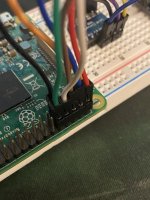
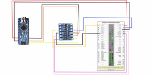
All you need to do is wire RX, TX, and GND from the Nano to the Pi's TX, RX, GND respectively. The Arduino Nano has 5V I/O though so you'll need to run it through a level shifter to keep from frying the Pi. The Arduino can be powered from the 5V pins on the Pi as well (plugged into the 5V pin on the Nano, not VIN).

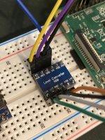
I purchased the following level shifter:
https://www.amazon.com/gp/product/B07LG646VS/?tag=tvwb-20

I've soldered the voltage level shifter together and plugged it into my breadboard and wired it up as i understood it to work. However when i'm in the linkmeter UI there is no device found and i get no input on thermometers. (granted i have no thermometers currently plugged in, i'd just expect wild temperature reading in the ui. Is that correct?

quickfacts:
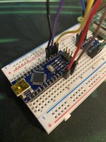
  1. Linkmeter device is an arduino nano
  2. voltage level shifter (see amazon link above on model)
  3. raspberry pi 3 v1.2
  4. Manually flashed heatermeter.hex to arduino using windows command prompt and command built using avrdude that comes with arduino software 1.8.13.
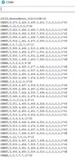
  5. Flash was successful and when observing the output from the arduino (see output screenshot) it looks to be functioning as expected.
  6. I am powering the arduino off the pi.
  7. Have confirmed 5v on the HV side of level shifter and 3v on the 3v side of the level shifter going to the pi.
update: added an awful wiring diagram i made with paint, but it's accurate. XD
 

Attachments

  • Arduino_LM_Output.JPG
    Arduino_LM_Output.JPG
    98.9 KB · Views: 16
  • IMG_0926.JPEG
    IMG_0926.JPEG
    160.5 KB · Views: 12
  • IMG_0924.JPEG
    IMG_0924.JPEG
    150.2 KB · Views: 12
  • IMG_0927.JPEG
    IMG_0927.JPEG
    153 KB · Views: 11
  • IMG_0928.JPEG
    IMG_0928.JPEG
    147.7 KB · Views: 15
  • worstWiringDiagramPlsDontHate.png
    worstWiringDiagramPlsDontHate.png
    202 KB · Views: 13
Last edited:
Fantastic progress! Good to see data coming out of the HeaterMeter Nano so that looks good. I've looked over the wiring and everything appears to be connected up to the right places, so it is strange that it isn't working. I don't have that specific level shifter, but it appears to be the same schematic as we use on the servo line so I can recreate it here and see if it works for me or if I run into some porblem.
 
I knocked it down to just the bare essentials:
  • Pi 5V (Yellow) to Nano 5V and Shifter HV
  • Pi 3.3V (Red) to Shifter LV (Brown too, oops)
  • Pi GND (Brown) to Nano GND
  • Nano TX (Blue) to Shifter H1
  • Pi RX (Orange) to Shifter L1
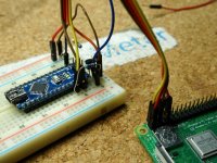
And it worked great. Maybe try removing the GND connections to the shifter, just one GND to the Nano, and start with just getting Nano TX to Pi RX working. Sorry this isn't the best picture but the connections are listed above. The component to the right of the Nano is a shifter (just a BS170 MOSFET from the HeaterMeter BOM) with the two 10k pullup resistors, which should be identical to one of your shifter's layout.

With this you'll probably see data in the graph (random analog data) or at least the clock on the upper right in gray and ticking, but the configuration page will say No HeaterMeter until the other RX/TX line is connected.
DSC07325.JPG
 
Hello again, I think i've tried to recreate what you proposed here but the results are the same. So, at this point i'm wondering if it's my pi. i know before i knew about the voltage difference between pi and arduino I did have the tx/rx hooked directly up to the pi while i was initially attempting to get it to work. So i guess my next question is "how do i know if i've overloaded my pi with the 5v from the arduino?" are there any fuses to check?
Thanks!
 
I don't think there are any fuses or any other protection on the lines.

The easiest thing to do is jumper the two pins on the Pi together, RX and TX, with nothing else connected. Open a terminal in one window and type `cat /dev/ttyS0` (it will just hang) then open a second terminal window and type `echo XXX > /dev/ttyS0` and when you press enter you should see XXX on the first window. If that doesn't work, you need a new Pi.
 
it appears my pi is fine. I was able to get the XXX output. i even set up a loop to make sure it wasn't just working intermittently and it never missed a beat. back to the drawing board i suppose.
 
When you had just the Arduino TX connected through the level shifter, did you try doing a `cat /dev/ttyS0` then or just check the home / config page? The home page may not show data if the Analog inputs on the Arduino are floating and they generate values which fail the sanity checks so they'll show as disconnected. Also make sure you stop linkmeterd to check because it will try to eat all the data it can.
Code:
/etc/init.d/linkmeterd stop
cat /dev/ttyS0

If that doesn't work you could try a good ole 4.7k/10k resistor divider on the Arduino TX line to see if that works where the level shifter doesn't.
 
Did you manage to get this going? I am having trouble getting printed boards in New Zealand in a decent time frame or cost so will just use an Arduino, Pi and hacky protoboard to get things up and tested while I wait for the real PCBs to arrive.


Back
Top