Dougie_Hess
New member
Hello everyone,
Frequent lurker but new member here. I signed up to get some input on a small hobby project I have started that might be considered a “HeaterMeter Lite”. I started this project as a way to learn about microcontrollers and electronics, and if I can make something useful then all the better.
Here’s the idea. The HeaterMeter does a great job with temperature control, remote temp monitoring, temp logging, etc… But I already have an ET732 for temp monitoring (as do many others) and all I really want is temp control. So I set out to design a blower system that picks up the ET732 radio signals to monitor temperature and PID controls the grill temperature from that.
I have successfully captured and decoded the ET732 radio signals using a cheapo 433mhz radio receiver and an Arduino Uno (or a Tiva-C Launchpad). Temperature packets are sent in 4X replicates every 12 seconds. From there I can write code to do some error checking and decoding to get the grill temperature (and meat temp, if I want).
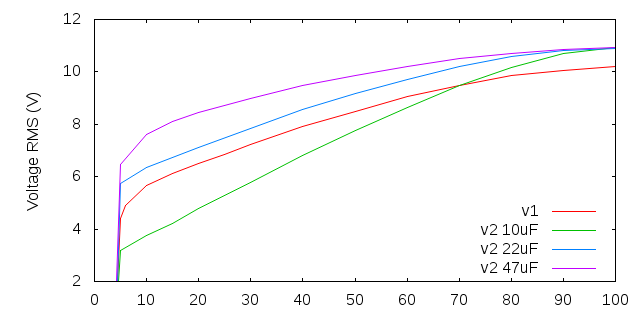
I bought a 12v brushless blower fan off ebay (model HT07530). It is a similar package to the HeaterMeter recommended one, but not exactly the same. I am hung up on getting good PWM control of this fan at anything less than ~95% duty cycle and this is where my knowledge of electrical circuits is failing me. I have tried various circuits involving a low-pass filter on the 5v PWM input, a TIP120 transistor, a IRF510 MOSFET, and/or a capacitor across the blower terminals. Still the fan stalls at lower duty cycles. So first question, for those more knowledgeable in such things… Will the circuit in the HeaterMeter schematics using a BC337 and a FQU11P06 likely work for this fan, or should I just suck it up and get the same fan everyone else is using? Also, any alterative to the FQU11P06 that I could get at Radioshack?
Second question is about PID update frequency. If I can only get temperature updates every 12 seconds form the ET732 radio signals, is the interval going to be too long to effectively control the grill temp in a PID loop?
Finally, I built a 3D printer a while back and have seen some really great blower / servo damper mounting designs posted here. It seems worthwhile to integrate a servo damper into my design. In terms of operation, could I just use the damper to regulate air flow by letting the blower run at 100% then PID tuning the damper, or is that going to be too taxing on the blower motor?
Sorry for the long post… glad to finally be a member! Hope I can also get some insight into high altitude grilling (I’m at 7200 feet), but that is a topic for another thread.
Thanks!
Dougie


