Version 2 of my homebrew controller


Originally posted by Ed Pinnell:
Bryan, I think, uses the Vin connection on the side of the Arduino. Check and see if +12VDC is present there when the Arduino is powered up from the wall wart. The only potential problem with doing it that way is that you are pulling the power through the PCB board traces, which typically can't supply much amperage before melting like a fusible link. It's not a problem in this instance, though, unless something should short out between Vin and the blower.
Yup, I just plug right into the Vin pin on the Arduino. The trace that goes from the power jack -> diode -> 100uF cap -> Vin pin is not huge, but it is larger than any of the I/O lines. I've not seen any problems with pulling 200mA through it to run the fan power circuit.

On the build I did for my Dad, I'm additionally running an LM7805 linear regulator through the Vin, but I used one of SparkFun's "Pro" Arduino. I do not recommend using one of these because for some reason they use a voltage regulator that can only put out 150mA (as opposed to the 800mA LDO regulator in a standard 2009 Arduino Duelmilnovakajigger).
 
Originally posted by Ed Pinnell:
One thing I would like to pass on, though, is the importance of having good air flow through the pit. If you have a couple of cooks without a thorough cleaning of the ash and other fines that tend to block the grate openings at the base of the pit in the Egg, air flow through the pit is restricted, and the system response suffers. I recommend a good clean and screen before a low and slow for optimum results, especially if your last cook was a 700* pizza cook!
I'm going to agree with Ed on this. Before I do any low-and-slow I clean out the ash really well because a big pile of ash down not only messes with air flow but can get blown around a bit if the fan is on 100% with the lid open.

Charcoal usage too. I use aaaabout 1lb every 6-8 hours. Are you doing your cooks at 250F, Ed? I'm still doing 220F, and am curious how much 30F affects the cook time.
 
Forgot to mention, I've been playing with the LCD code a bit and built a breadboard test setup. If you're ordering parts from Mouser, this Newhaven NHD-0216K1Z-NSW-FBW-L is pretty sweet. It have a built-in resistor for the backlight so one less component, and because the backlight only draws 20mA (tested in my setup to only draw 17mA) you can drive it from the Arduino. The benefit of that is that you can dim or turn off the backlight using PWM or just digital I/O. It is also 25% cheaper, and has its pins brought to both the top and the bottom of the display for easier hookup depending on your orientation.

Ed, for your shift register, did you use a 74LS164 or 74HC164 and in 2-wire or 3-wire configuration? My HeaterMeter I used a 2-wire and I'd have occasional issues with the display getting messed up until I added the "Long PWM" code. I can reproduce the same problem with my test system only in 2-wire mode.

Lastly, I've calculated the cost of building the HeaterMeter I made for my Dad: $60. This includes the Arduino chip and needed parts, blower fan, 5V supply, 12V MOSFET section, thermistor, mono jacks, LCD, project box, and buttons, and other misc parts. WiFi support adds $63. He already had the probes ($12/ea) and a 12V wall adapter (~$8). A very economical project if you've already got a soldering iron and some bits of wire and breadboard around the house.
 
Originally posted by Ed Pinnell:
Bryan, most LCD displays make a claim to be HD44780 parallel interface chipset compatible...this one apparently does not, but I have a strong suspicion that it is. In your testing, is it a direct replacement for the LCD in the parts list?
Oh snap you know I didn't even bother to check that it was. I looked at the pinouts and saw they were the same so I just assumed. This LCD uses a SPLC780D controller, which has the same commands, features, and timings but it looks like it has a different character set for the non-ASCII characters. It actually is much nicer because it has arrows and some math symbols but of course the degree symbol is in a different place. This is just from me looking at the datasheet, my test app doesn't use the degree symbol so I hadn't noticed. Other than that it is a drop-in replacement except you don't need R14 between 5V and pin 15 on the LCD.

I think I've found the issue that was causing my LCD to get all garbled from time to time when the fan was set at a PWM of around 6/255 (enough that it twitches but doesn't actually turn on). Here's the power line to the shift register in red and the yellow is the pwm pulse (at 50% scale).
spiketest-1bare.png


So it seems that pulling power on the 12V line drags down the power to the shift register IC below 4V. I was actually seeing it below 3.5V on some pulses. The datasheet for the IC says minimum supply voltage is 4.75V so this would be way below that and probably could prevent normal operation of the chip and therefore cause the LCD to get out of whack. So step one was to add a decoupling capacitor by the IC. Looking around the internet, apparently you're supposed to have 1 0.1uF ceramic capacitor across the power lines of every 1-3 TTL ICs, depending on the complexity of the IC. I left this out of my design so clearly it should be added. That removed the largest parts of the spikes on the edges of the pulses, so now I'd rarely see it drop below 4V.
spiketest-2ic.png


To get rid of the big sag, I clearly needed more juice to the whole system. For that I connected a 330uF electrolytic between the 5V and ground by the power supply. Here it is with just that, no bypass.
spiketest-3pow.png


You see the spikes are back, but the sag is gone. So the proper solution is of course to use the bypass capacitor for the TTL IC and bolster power supply with the electrolytic.
spiketest-4both.png


The spike there is actually the worst case I could find, whereas all the earlier images were actually happening continuously. Most of what I was seeing with the 2 additional capacitors in place are straight lines with tiny jaggies at the PWM on/off points.
 
Originally posted by Ed Pinnell:
You are pulling your 12v through the PCB trace and a blocking diode. The diode drops the voltage some. I get my 12v from the source. I wonder if you moved your 12v line if that would eliminate the sag?
Yeah the diode knocks off about 0.7V but from there it is a straight shot out the barrel jack to the wall wart. I forgot to say that the scale on the graphs is 10uS/division so the entire sag will recover in 50microseconds. My 5V supply is slightly different than the one on the Duemilanove but their characteristics should be similar. I need to do some testing to determine exactly how much current the fan is drawing when the kickstarter is trying to unsuccessfully start the fan, but it seems to me that the capacitor fix works because I've had this thing running on my desk all day without the LCD getting messed up. The test just slowly cycles the PWM from 0 to 10 (out of 255) and back down to 0.

I bought a Owon PDS5022S oscilloscope because it is probably the cheapest one available without taking a chance on a used device. It does a good enough job and costs only $270 compared to like $2000. Macrovision scrubbing... geez, Ed, is there anything you haven't done before?
icon_smile.gif


All this circuits talk, I forgot to comment about your cooking! There was also a sale on prime rib here around Christmas time, so that is also what we had. I didn't have as much time to prepare so we did a 300F indirect heat on the Egg just over some oak. Man I think I just started salivating all over again. You're right about so many things to cook and so little time. I keep trying to figure out how to have delicious BBQ waiting for me when I get home from work. I'd think spareribs would dry out in the 11 hours from when I leave to when I get back home, but isn't enough for a butt. I think I'm going to try like a 4lber and just manually set the grill to hold temperature when the meat is done.
 
Dang it.. I was all ready to head down this road and then I found people decoding the Oregon Scientific wireless temp and rain gauges with Arduino's.
Then I found the $30 444mhz usb \ serial modems for the PC's. As temp control isn't an immediate need for me with the Traeger, I'm thinking of just buying the new Maverick smoker thermometer and just having my PC do the logging over 444mhz.

Issues: I can't find anyone that has attempted to decode Maverick's wireless language.
I loose the ability to look at the pellet hopper level.

Back to google.
 
Originally posted by Bryan Mayland:
geez, Ed, is there anything you haven't done before?
icon_smile.gif

I've been thinking that same thing for a while now!

Hey guys,

If you recall the issues that I had a while back, I found out my breadboard is bad, and by bad I mean bad in multiple connection points. It's no wonder I couldn't troubleshoot the **** thing! I think with my next attempt I'm just going straight to soldering on a board. I'm pretty confident that I understand the wiring after spending so much time debugging. Thanks again for all your help.

I'm temporarily re-purposing my Arduino and WiShield to monitor the temperature in my basement for the next week or so. I'm working on getting it setup to monitor the ambient air temp and make sure it stays at or above 48F so my pipes don't freeze. We have wood and oil based heat but the wood stove has been going for 3 days straight and when it does the heat doesn't kick on. They are calling for temps of around -15 to -20 this weekend in VT.

btw, I got $20 from SparkFun's freeday this year. I could have had more but had to jump into a meeting at work right in the middle of the questions you had to answer for $10 each. I got 2 right, submitted the 3rd, and then ran off to my meeting. The 3rd timed out and never made it through. Oh well. Can't complain about $20 off.

I've been watching the thread intently even though I haven't been responding. This thread is going to become a book. Do we have a record yet on tvwbb?

- John
 
Originally posted by Ed Pinnell:

HeaterMeter + Weber Kettle + Rotisserie + Spare Ribs + Low & Slow + Graphs & Such

EDIT: Errr...forget the Graphs & Such. I still haven't figgered out how to make the HeaterMeter go 'round and 'round on the rotisserie.

Looks like this is a good project start for the wireless temp probe. I stumbled onto it while looking for my wireless decode of the Maverick language.

http://www.arduino.cc/cgi-bin/....pl?num=1294511428/8
 
Originally posted by Ed Pinnell:
Geez, Bry, I thought we had this resolved back at the end of October with HeaterMeter r39 ("-- Added MINIMUM_FAN_SPEED define")

A 330uF cap has got to be the biggest component on the board now. Do we really need to twitch the fan at 6/255 (2.3%)??
Yeah that software fix worked for me but I was always curious what caused it. I just used a 330uF cap because I had one in my box, and the 6.3V version isn't very big at all. Especially in the case where you're making your own 5V power, it would be worthwhile to use that in place of a 100uF.
Might add that this decoupling cap is considered good practice and needs to be located as close as physically possible to the power pins on the IC.
I'll probably add this to the schematic because it should really be there even if it works ok without it. Less chance of something going wrong, right?

1st up: blower mount. Reuse what I have, and wished I woulda done it differently the first go-around.
Oh do go on. I liked your last design and it worked great for my Dad's. I was planning on making one for myself to replace the cardboard prototype but if you have a new idea I'm excited to see what it is.

I've also been reworking some of the HeaterMeter code to make it a little more organized, like moving the menus and stuff to their own files. I've also slimmed down the code about 1kB or so and removed the ability to edit the probe name from the menus. It was such a pain to do, used about 500B of code, and if you want to change them you can still just recompile with different defaults.

These changes gave me plenty of space to implement the Alarm code and add the menu items for them. I've changed the menu layout slightly so instead of going -> -> -> through them all, you have to press down to enter a probe's config. I think that makes it a bit easier to get through now that there's a LOT of items in there. Each probe (except ambient) has a high and a low that can be enabled separately.

I've also got some ideas about how the serial interface will work. To get started, I dropped an XBee module in my original HeaterMeter and attached another to my Linux box so they are virtually like a DD-WRT router hooked serially to the controller. That should really speed development of the scripts and any code that will be written, rather than having to edit/build/upload to the router each time I want to make a change.
 
Thanks Ed. I've tried working directly on the router but I found it to be a pain to edit things on it or to edit it locally and publish it to the router. I had the XBee modules just sitting around so it seemed like a pretty good idea, and I'd actually get to use them for something.

This is all thinking outloud here.

First thing I'm working out is the serial protocol. I think the general idea is that it will follow the NMEA GPS protocol design. Here's what a sentence looks like:
$(tag),(csvdata)*(optional checksum)CRLF
(tag) a 5 character code indicating what data follows. The first 2 characters are always HM and the remaining 3 are the sentence type code.
(csvdata) CSV data. The only difference is that data that is not valid will be blank instead of 0.

Tags from HeaterMeter to the client
HMSTS - "status". This is the basic CSV message. I'm wondering if this should be in Celsius regardless of what the HM is set to. I think I want to reorder it though to support the possibility of more probes. Maybe this can be split into to messages? HMTMP for temperature HMFAN for fans?
HMLID - Lid timer information. Fields are lid ID, time remaining. So like on would be $HMLID,0,240* and off would be $HMLID,0,*
HMALM - Alarm trigger. Not sure what's going to go in here.

Tags from Client to HeaterMeter
HMSET - Set setpoint. Fields are for controller number, setpoint in degrees, and optional units. C is assumed if not sent

Aww crap a friend is coming over. I'll have to pick this up later, but the idea is that the settings will have their own tags or something. Let me know what you think and what sort of features would be nice here.
 
Hi folks,

I thought I'd drop in a note to thank y'all for the work you've put into this project. I've been looking into an Arduino-controlled electric flowerpot smoker for a while and this thread has been a wealth of great information.

I fired up my "Robosmoker" over the weekend and made some killer BBQ without having to babysit the smoker for the 13+ hours. Amazing!

As some background for anyone interested in going the electric route, I have basically just used the Heatermeter schematics except I swapped out the DC fan bit for an optocoupled triac that controls the wattage of a heating element. Works OK (+/- 5 degrees), but since my circuit is probably not very well-designed and there's pretty poor linearity, I'm going to try PWMing a SSR to see if I get better results.

I'll add that I had no luck getting the LCD working with the 74HC164N shift register. I read that the LS chip seemed to be more reliable than the HC, but this didn't work for me either (in 2 or 3-wire mode). I just ended up using a serial-enabled LCD instead. Works OK but there seems to be a conflict with using a software serial library and the WiShield 2.0. Instead I hook up to the serial Tx pin on the Arduino.

Cheers,
 
Daniel
I too use an electric (SmokinTex 1400) and am trying to develop with an Arduino Mega. I'll be interested in your ideas and implementations.

Curt
 
Originally posted by Ed Pinnell:
<BLOCKQUOTE class="ip-ubbcode-quote"><div class="ip-ubbcode-quote-title">quote:</div><div class="ip-ubbcode-quote-content"> Works OK (+/- 5 degrees), but since my circuit is probably not very well-designed and there's pretty poor linearity, I'm going to try PWMing a SSR to see if I get better results.

My guess is that you might also be able to adjust the PID to the characteristics of your electric burner (which responds much slower than a blower). I think it would be informative if you could plot what the "average fan speed" (electric burner) is doing versus the "actual fan speed"...I'm thinking you may not be turning the burner on for long enough to appreciate any gain in heat, in which case an SSR wouldn't help.

There is no "one-size-fits-all" PID setting...each system is unique and needs to be individually tuned for optimal response.

It would be nice to set the software up so that you could adjust the PID on the fly and do some R&D. </div></BLOCKQUOTE>

Good point. I developed some Aurdino PWM code that uses longer on/off cycles than the Arduino inbuilt hardware PWM (< second). Let me know if you are interested.

Curt
 
I hope folks don't mind me cluttering up this thread with talk of electric smokers. If so, I'm glad to move this over to a new post, just let me know.

Curt- I just checked out your page on your smoker- very cool stuff!

This is my first foray into Arduinos and I'm not a programmer or an electronics wiz. Attempting to do this was either ambitious or just plain dumb. In fact, I quickly learned that I could probably just learn to roll most of my own code in the time it'd take to understand everything in the Heatermeter code- so that's just what I did. I'll be glad to share my code, but it's probably laughable to anyone with a clue.

As for my hardware, I'm using an Arduino Uno, WiShield 2.0, and a 20x4 serial LCD (http://www.sparkfun.com/products/9568). Since I'm using PIDLibrary (http://www.arduino.cc/playground/Code/PIDLibrary), I use the Processing front end for charting, PID tuning, and logging. Unfortunately, I was having trouble using Processing charting with the LCD and WiShield at the same time so I just disable the LCD/Wishield as needed.

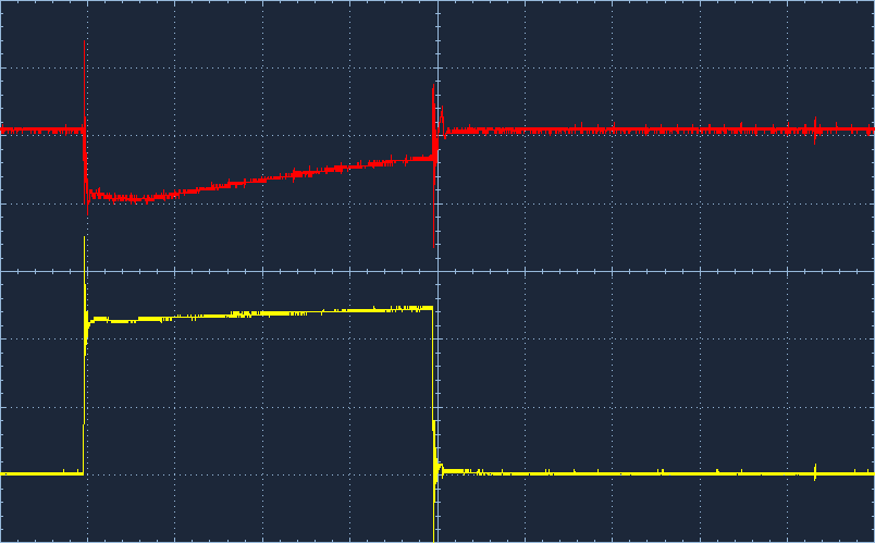
Ed- thanks for your feedback. Tuning the PID controller took a bit of guesswork and I feel like I have something OK, but not great. The biggest problem I'm running into is overshoot when first starting up the smoker or after opening the lid. As a workaround, I can switch the PID off and go manual as needed to sort of get the PID about where it needs to be. Also, I hate to risk a good BBQ by tuning the PID while food is in it, but that might be necessary to really get it dialed in.

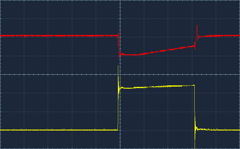
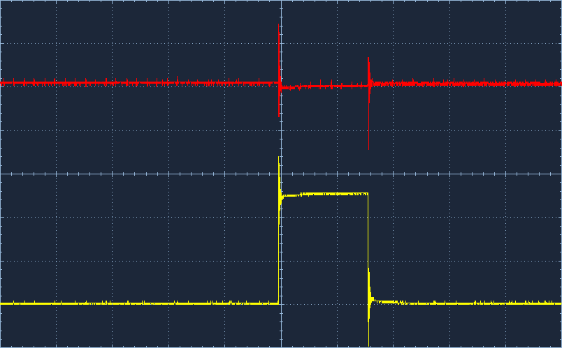
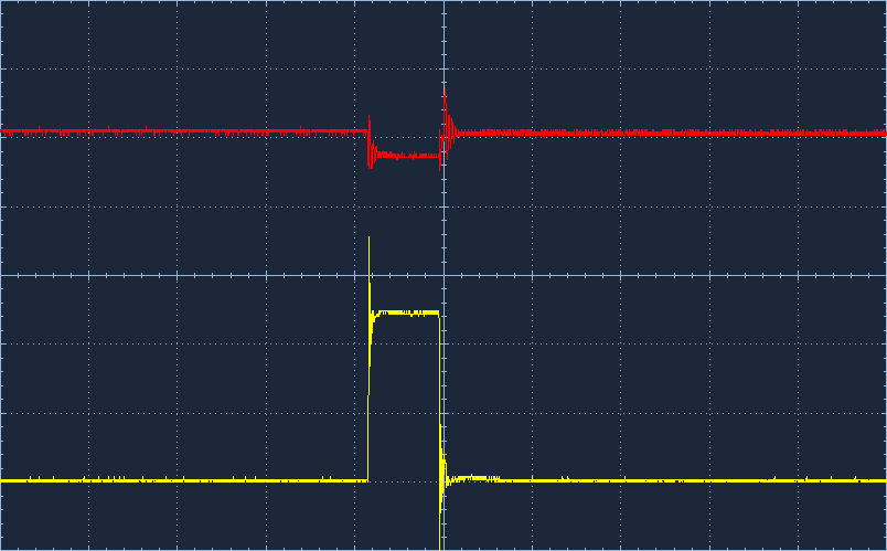
What I've been using instead an SSR is a triac (http://www.harborfreight.com/router-speed-control-43060.html) but instead of the pot I wired in an optocoupler (VTL5C2). I just pass the PWM through a simple cap/resistor filter to control the optocoupler. This gives me pretty good control over the heating element and it's never truly turned off so the smoke output is consistent. The main problem I have with this is that the optocoupler has logarithmic response so I lose what little fidelity PWM gives me (I use PWM from 80-140) and I think it makes the PID less reliable.

I have no doubt that someone with some real know-how could design a better circuit that really takes advantage of the triac. Something like a transistor controlled triac?

In the meantime, I have some SSRs on the way and I'm curious to see how this compares to the triac. Any idea of what kind of consistency we can get out of that setup, Curt? I saw some other folks mentioning having luck with as high as 10 second duty cycles on another forum…

Daniel
 
Originally posted by Ed Pinnell:

I'm thinking that you may not be turning the burner on for long enough to appreciate any gain in heat, in which case an SSR wouldn't help.

I think you should be thinking in terms of duty cycle rather than PWM in the classic sense...in other words, 90sec on, 10sec off would be 90% duty cycle, 10sec on 90sec off would be 10% duty cycle. Remember that the burner is essentially a resistance coil and by using PWM you are making the burner think the input voltage is low. It can't overcome the resistance to actually cause any heat to be given off, and the hotter it gets the higher the resistance and the poorer the response with PWM.

In other words, you need much longer "on" times than you are actually getting to make it heat up.

90 seconds may be too long, my smoker can move a number of degrees in that time. By cycling on/off regularly the the heating element never cools off or heats up to extremes. This may keep the control much tighter because of the increased stability.

Curt
 
Sorry for some duplicate data here - I was having issues with the WEB server.

In the meantime, I have some SSRs on the way and I'm curious to see how this compares to the triac. Any idea of what kind of consistency we can get out of that setup, Curt? I saw some other folks mentioning having luck with as high as 10 second duty cycles on another forum…

Daniel
My time has been taken by non-bbq activities for the last couple of months. When the weather breaks, I will be spending much more time on this project.

I haven't done any testing with my PWM logic other than verify that the timing is correct, or close to it. The PID controller has cycles in this range (and longer). To muddle things further I am developing my own PID replacement algorithm.

I think you should be thinking in terms of duty cycle rather than PWM in the classic sense...in other words, 90sec on, 10sec off would be 90% duty cycle, 10sec on 90sec off would be 10% duty cycle.
90 seconds may be too long, my electric smoker temperature can move a number of degrees in that time, especially a low smoking temperatures. The PWM logic actually uses a longer cycle (8-10 seconds) in the 30%-70% duty cycle range and a shorter cycle at the duty cycle extremes. This is to prevent long periods of on or off cycles.

Curt
 
Oh! Good detective work there Ed. Actually the problem is that if there's no probes plugged in, it is supposed to just show the top row of the Home screen and blank out the bottom row. There's a bug in the Home display that prevents it from doing anything though, followed by a pretty hilarious typo bug which through all my years of C experience I have no idea what the code would actually do.

Anyway, if you want to fix it change the first line of void updateDisplay(void) from
<pre class="ip-ubbcode-code-pre"> if (Menus.State < ST_HOME_FOOD1 || Menus.State > ST_HOME_AMB)</pre>
to
<pre class="ip-ubbcode-code-pre"> if (Menus.State < ST_HOME_FOOD1 || Menus.State > ST_HOME_NOPROBES)</pre>
Also take this bug out by replacing<pre class="ip-ubbcode-code-pre"> buffer[sizeof(buffer-1)] = 0;</pre>
with<pre class="ip-ubbcode-code-pre"> buffer[sizeof(buffer)-1] = 0;</pre>
 
There's still the issue if you compile with HEATERMEATER_NETWORKING and don't have a WiShield. It doesn't check to see if you have one, it just waits for it to initialize. If you don't have one, make sure to disable it during compile.


Back
Top