The circuit isn't that complicated really, so maybe take a jumper wire and CAREFULLY make the connections where the traces should be to see if you can locate a problem?
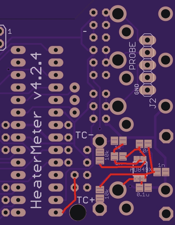
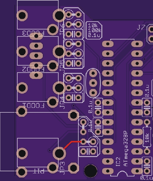
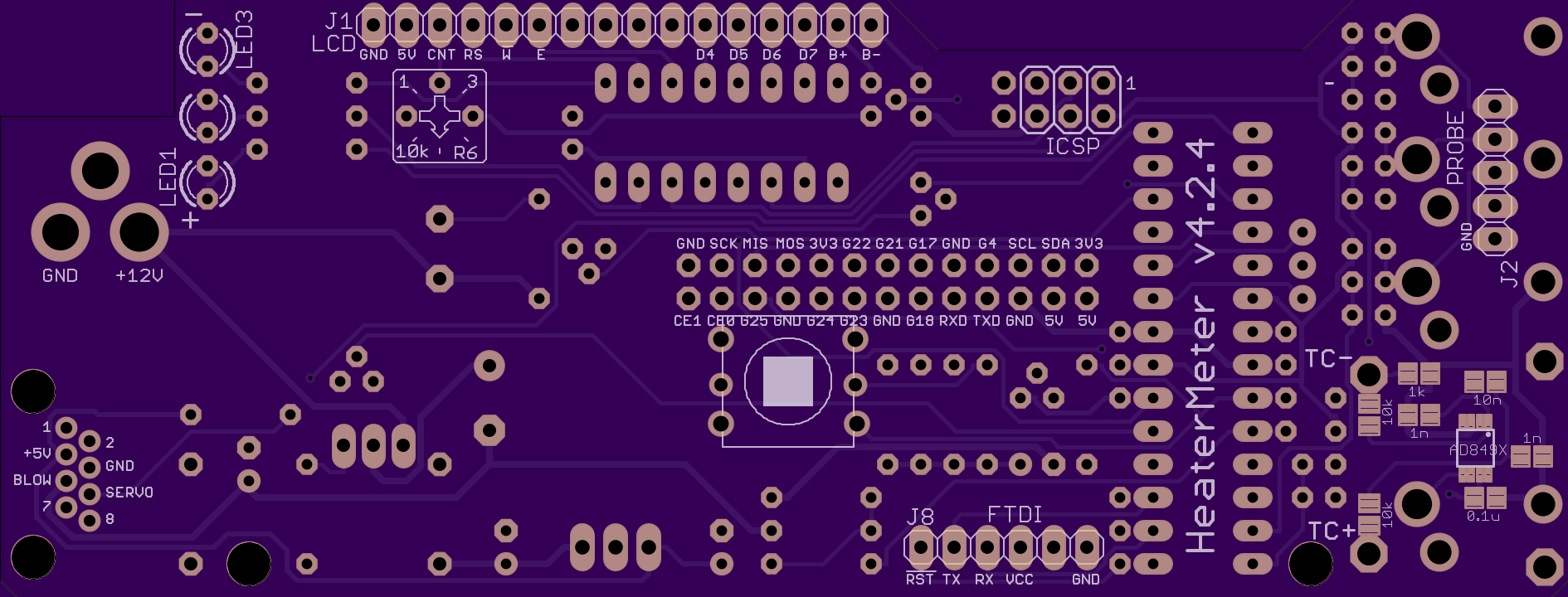
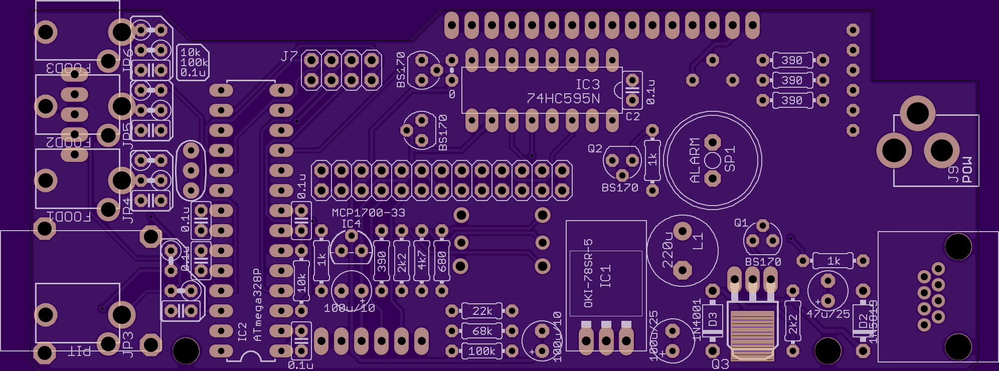
Looking at the images of the board from OSHPark posted below you can follow the traces, save images to zoom in on the area in question
Notably, the output of the TC AMP (the two pins that are bridged on the end of the chip) goes to the (unused) hole for the standard probe, from there to the other side of the board where a trace goes over to the 100K resistor (as well as to the probe header, so check that area for anything that looks funny too). So, take a jumper wire and go from the end two pins that are bridged and tap the end of the 100K resistor that is furthest from the ATMega.... Does that fix it? Then, from the other end of the 100K resistor it goes over to the corner pin of the ATMega, so move your jumper there, fixed? Try directly the the pin on the ATMega (rather than the socket), fixed? That traces the output of the tc amp, you can do the same for the input if you dont find an issue on the output... You could trace this down with the continuity function of a multimeter rather than jumper wire as well... That would verify the board is good or bad.
Otherwise, you may have a cap in the wrong spot, I can't seem to find any indication of what is what on the caps, so no way to verify visually, so you have to either replace with known values or test with a meter (most likely the cap would need to be out of circuit to test). Did you use lots of flux when you soldered the tc amp? Maybe there is gooped up flux under the chip that kinda shorts things out? Some flux remover spray might help for that, or a repeated flushing with alcohol maybe.