You are using an out of date browser. It may not display this or other websites correctly.
You should upgrade or use an alternative browser.
You should upgrade or use an alternative browser.
Rotordamper Aux. TC board with two probe jacks, blower and servo connections
- Thread starter John Bostwick
- Start date
")


Yeah, its behind the probe jacks, header itself is not soldered on yet
Ok I see where you mean that great!
RalphTrimble
TVWBB Diamond Member
John, On the probe jacks...
The pin closest to where you plug in the probe is the GND, the middle pin is the output, the back pin is the switched leg. So you want to put gnd to the front pin, and use the middle pin as the output. I guess you figured that out already, but I thought I would elaborate because I recall going round and round with someone about this a while ago....
Also, I expected the board to go together with the layout like the mock-up pictures I sent you, with the probe jacks, TC jack and CAT5 jack all in a row on the same side of the board. I will have to see how this layout with the CAT5 jack on the other side of the board will work out, I wasn't expecting that. If they were all in a row that makes it easier to fit the board into the RD....
John Bostwick
TVWBB Wizard
Yeah, but i just followed the same schematic from the heatermeter, basically just copied and pasted the jack. But, I think when I had to change the footprint I might have reversed the pins.
RalphTrimble
TVWBB Diamond Member
OK, well, we'll have to trace down the circuit because the TC jack does have a + and - ... so that will dictate which side the jack needs to be on I guess. I was about to say you don't want to put the TC jack on top of the TC amp, cause you don't to warm up the TC amp, but the whole deal is the the TC jack and the TC amp should have the same ambient temp so it might still work out fine.
When I have the boards in hand I will evaluate the layout and make suggestions, seems these are workable but we should fix the probe routing and tweak the layout a bit to make it integrate with the RD better...
When I have the boards in hand I will evaluate the layout and make suggestions, seems these are workable but we should fix the probe routing and tweak the layout a bit to make it integrate with the RD better...
RalphTrimble
TVWBB Diamond Member
On the difficult to solder trim pot... There is a huge amount of flexibility on that part. We could use other than 1M, and could prob get away with a (cheaper) single turn trim pot, just need to set the range properly with the resistor in series with it. We're just splitting up 3.3v to provide a small adjustable voltage to the op amp. So we can pick something different for the trim pot, type, value style all very flexible....
John Bostwick
TVWBB Wizard
Version 3.4 and hopefully the last version lol.
Nothing added just cleaned it up a bit and added some Values to help with soldering and also moved the Tc to the same side as the jacks and cat5 connector.


Nothing added just cleaned it up a bit and added some Values to help with soldering and also moved the Tc to the same side as the jacks and cat5 connector.
John Bostwick
TVWBB Wizard
Updated first post, as being shared on OSH and part list needed to build
RalphTrimble
TVWBB Diamond Member
My first RDTCv3.3 board went together really well, powered up and worked perfectly first time around. The board is really nice, great work John! I built it up without the 3.3V Regulator or REF offset circuit because I want to do some testing with the TC running at 5VDC VS 3.3VDC from the regulator. Initial tests show the TC offset by about 2-3 degrees when running the TC amp on 5VDC, not too bad and can be corrected with offset. I have yet to test in boiling water but it seems to track well with known good probes. I tested the two standard probes, TC, servo, blower and there is no noise coming from the board, it works really nice....
So nice I decided to throw together a stand alone box for the board:
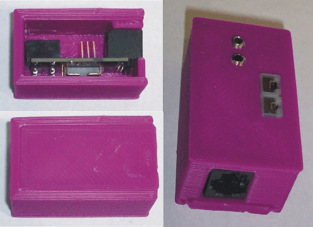
This is a rough first draft of the box, I will refine it with a few tweaks and call it done....
EDIT:
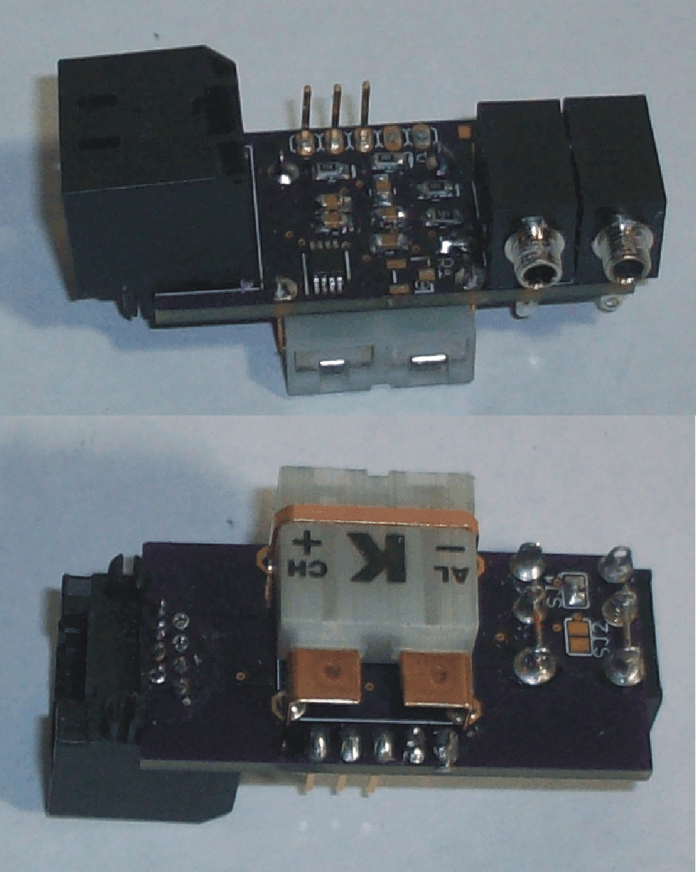
I just realized that there may not be a pic of this version of the board posted yet, so here's a shot of the top and bottom:
So nice I decided to throw together a stand alone box for the board:
This is a rough first draft of the box, I will refine it with a few tweaks and call it done....
EDIT:
I just realized that there may not be a pic of this version of the board posted yet, so here's a shot of the top and bottom:
Last edited:
Dan Francis
TVWBB Fan
Hi John, I have 3 of your 3.4 TC Amp boards coming tomorrow I will use with my much modified HM 4.0. I may have missed it but is there a drawing somewhere that lists which of the 5 pads for servo/blower are which? I need to run them to a cat5 jack then use jumper cable to blower as that is the way my servo/blower is already set up with built in cat5 jack. I probably can figure it out with a meter but if you have a few minutes to post which is which it would really help. I am going to switch the pullup resistor to use a thermocouple for the pit. Thanks
RalphTrimble
TVWBB Diamond Member
If you look at the roto damper thread I recently posted a diagram that details all of the CAT5 connections for various configurations. Just follow the pin numbers from the diagram... The inner 4 pins on the CAT5 jack are used for the servo and blower, the outer 4 pins are unused by the HM, so those pins are used for the probes....
Dan Francis
TVWBB Fan
Thanks Ralph, I did see that. My question is on the 5 pads on the TC board which go to the servo and blower. My understanding is that the cat 5 jack on the TC board will connect to my HM. I need to add another cat 5 jack to TC amp to connect my servo and blower as I already have it wired with a built in Cat5 jack. I think you hard wire the RD to these pads, mine will be through a cat5 jumper. I am using your standard pinout as you listed but just need to know which pads on TC amp are 12v, 5v, servo and grounds. Thanks again to both of you for your work on this TC amp!
Dan Francis
TVWBB Fan
Maybe I have it all wrong and the TC amp board doesn't have connections for blower/servo. I just assumed for some reason those pads were servo/blower connections from incoming Cat5! If that's the case, sorry for my ignorance!
RalphTrimble
TVWBB Diamond Member
Yes, Dan is wrong...
The TC board has EVERYTHING on it.... You solder the same CAT5 jack that is found on the HM board onto the TC board and then just use a straight LAN cable to connect them. There is a header on the TC board to connect the servo, and the blower, and there is also an option to install an optional 3.3v regulator and a TC REF offset circuit if you like....
As far as where the pins go on the TC board, SAME AS THE HM BOARD.... Follow the pins on the CAT5 jack and compare them to my chart. For the blower and servo you can look at the silk screen on the HM board for what pins go where...
EDIT: you said 5 pads that go to blower and servo... Its not 5, its 4..... GND, 5V, SERVO Pulse, Blower +
The inner 4 pins go to the blower/servo, the outer 4 pins are used for the probes.
DOUBLE EDIT! If you have a HMv4.0 you will have to do some mods to either your blower circuit, upgrade to at LEAST the v4.1 blower circuit so the servo and blower can share a gnd... OR you can mod things on the RDTC board to match your HMv4.0 wiring....
Last edited:
Dan Francis
TVWBB Fan
OK, I can see I'm not making myself clear at all! Not your fault! But if you look at 3.4 board there are 5 PADS. They should be 12v, 5v servo signal and (2?) grounds, one each for blower and servo (yes I know they are the same ground 4.1 and later). I AM NOT asking ANYTHING about the Cat5 jack on the board! I just thought I would ask a quick question to John which is which. I will use a meter and figure it out myself. Thanks anyways. Dan
John Bostwick
TVWBB Wizard
The 3.4 boards are kinda a pain in trying to figure out the different components and connections. You are correct that there are 2 grounds.
So if you take your multimeter and probe the 5 pads, the grounds will help you figure out the way the blower and servo are connected. I believe the order is left to right 12v,GND, Servosig, +5, GND
On the newest boards that I will be testing this weekend, there will be no need to guess the connectors and it will have a locking header and labeled and has a space between the servo and blower connection. Also all the components have been labeled, so more guessing and double checking with a multimeter. I spent quiet a few hours learning Eagle these past few weeks and the new Version 5 boards will hopefully work great.
Last edited:
Dan Francis
TVWBB Fan
Thanks John! That will help a lot. Since I had to buy 3 boards I bought 3 sets of components. Think I will only build one 3.4 and save components for newer versions! Thanks for all your efforts on this, it is really fun to build this stuff.
John Bostwick
TVWBB Wizard
Antti, you might want to post this in the correct thread, or start a new thread.