New build - LCD question


CSchaaf

TVWBB Member
I just (mostly) completed my HM build - I don't have the case yet, so I haven't soldered the LEDs.

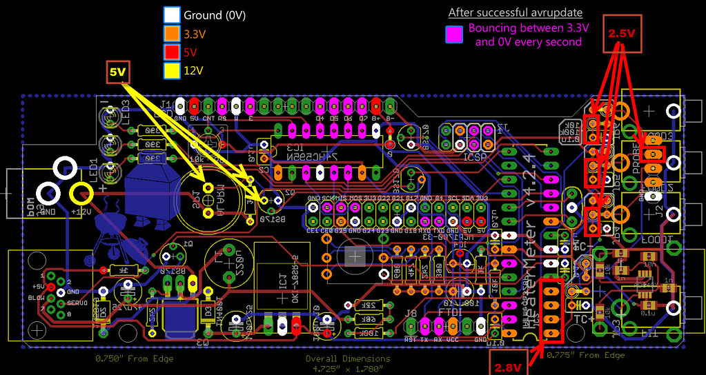
I powered up using the RPi USB connection and the LCD doesn't turn on - should it? Or do I need to use the 12v power to get the LCD active?

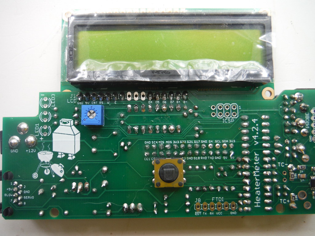
Also, apparently I can't count to 6 and when I built the connector for the LCD screen, I populated pins 1 - 7 (as well as 11 - 16). Will having a pin in #7 cause me any issues?

Thanks!
 
the extra pin is not a problem, you can populate the entire header if you want.

Did you install the backlight jumper for the LCD on the HM board? It should light up... but maybe not, as the backlight is actually controlled by the ATMega, and if it hasnt flashed then IDK what the LCD backlight might decide to do...
 
I had already flashed it and the LCD wouldn't light just using the RPi USB power.

Today, I configured the WiFi (it never would find the WiFi network that I wanted to use, but it did connect to the other two in the house - one might be close enough to reach my grill, I'll try that once I get the case)

I powered up with the 12v HM connector and the LCD lit up, but I only get blocks on the screen.

Also, I don't get any result on the web graph. I plugged in 2 probes and I don't get any temperature readings.

I posted pictures of my board here:

DSCF2275 by cschaaf33, on Flickr

DSCF2272 by cschaaf33, on Flickr

DSCF2273 by cschaaf33, on Flickr

DSCF2274 by cschaaf33, on Flickr

Any suggestions appreciated.

Thanks!
 
Last edited by a moderator:
It sounds to me like Linkmeter is alive on your rPi but it is not communicating with the HM board, and the ATMega is likely not flashed at this point. Did you try adjusting the contrast pot on the HM board?
 
Yes, I adjusted the pot. There is a VERY small range where I see the black squares - otherwise, the screen is blank.
 
Looking at your board the solder on the LCD contrast pot looks very poor. I would remove the majority of that mess and get it soldered in accurately will less solder. I can see some resistors where the hole through the board looks completely hollow, so I would go through the entire board and touch-up solder where you see it didn't flow to both sides of the board. I would also remove and reseat the ATMEGA IC, and probably reflow the pins on that socket while it is out for good measure.
 
Ha, I thought I did pretty well with my first solder job. I knew it wasn't a great job, but didn't think it was that bad.

I tried going back through and reflowing all of the points. Still couldn't get the LCD to display.

I tried going through the voltages and was getting some odd readings, like a 7v where the schematic shows 12v. Then, I accidently touched 2 pins and the LCD flashed and only half of the screen had black boxes. It slowly faded out.

I'm afraid the thing is toast now. Even if it isn't, I have no clue what to do next. I'll try to completely remove the pot and the ATMEGA IC, but I'll save that for another day. Too frustrated to continue at this point.

I even thought my vision was pretty good before I started this project, now I have to re-think that.
 
Sorry to hear you had a mishap....

At this point you need to assure the basics, starting with power. I would remove the rPi and ATMega,

then measure your 12VDC at the power jack

then measure the 12VDC at the OKI 5V regulator

then measure the output of the OKI regulator looking for +5VDC

then measure the +5VDC on the input of the 3.3v regulator

then measure the output looking for 3.3VDC

If anywhere down that chain you do not see the expected voltage that is where to start troubleshooting.

If you see all voltages as expected I would reinstall the ATMega and power the unit, see what happens. next the rPi... what happens?

A mishap like this is not the end of the world, the most expensive part on the board is a couple bucks, and the only one that is really tough to replace is the shift register...
 
Last edited:
Don't panic! There is always a logical next step, even when you have a mishap like that. Stick with it, you'll get it.

As far as the wifi, sometimes things are goofy. Different encryption methods can play a role, and every one in a while I come upon a WAP and wifi client that for whatever reason just don't like each other....
 
I had already flashed it and the LCD wouldn't light just using the RPi USB power.

Today, I configured the WiFi (it never would find the WiFi network that I wanted to use, but it did connect to the other two in the house - one might be close enough to reach my grill, I'll try that once I get the case)

I powered up with the 12v HM connector and the LCD lit up, but I only get blocks on the screen.

Also, I don't get any result on the web graph. I plugged in 2 probes and I don't get any temperature readings.

I posted pictures of my board here:

https://flic.kr/p/wQd3Zk

https://flic.kr/p/wPtHhq
https://flic.kr/p/vTbPoo
https://flic.kr/p/wxHEDK

Any suggestions appreciated.

Thanks!

What we know here so far is the above, in addition to the fact that the HM LCD did not come on during the first power up, and subsequently came on with black boxes.

I suggested perhaps the rPi hasn't flashed the ATMega for whatever reason, but was told the ATMega was already flashed. That kinda leaves me to question, was it flashed in another HM board or in a programmer?... since the LCD has not worked and you do not have LED's on this board you would have no way of knowing what is going on with the ATMega on this board.

You indicate that you have connected via LAN or WiFi, but there is no temperature data, and black boxes on the LCD.... Sounds like an unprogrammed ATMega to me? Or at least like the rPi isn't talking to the ATMega?

IMHO you are putting the cart before the horse with the Wifi... You've connected to the rPi and got into the HM config, but all indications are that the rPi is not communicating with the ATMega.

And now you may have hosed up something by shorting it out, or maybe not....

When you get back down to it follow the suggestions I had made to verify the power supply on the HM board for all voltages and report back the findings. Also please let us know "HOW" the ATMega was flashed since this HM board seems DOA so far to me... I don't see indications of display problem, I see indications the HM isn't functioning at all.

This isn't rocket science here, if something did burn up we can figure it out and replace it cheap enough.
 
Last edited:
Thanks for the support, Ralph and Chris, it is much appreciated!

I hope I have some time tonight to sit down and check my voltages.

Ralph - to the best of my knowledge, the ATMega chip has never seen another socket - HM or otherwise.

I got the HM kit Friday afternoon and got most of the components soldered that night. On Saturday, I finished up the build, downloaded the software, popped the SD card in the rPi, mated the rPi to the HM, and used the USB cable to power the rPi.

The instructions said the LCD should come on in about 30 seconds. When that didn't happen, I let it go for about 5 minutes before trying anything else. Since I didn't have the LEDs, i figured I would let it go on its own and see what happened. The LCD never came on at all, even when I twisted the pot slowly in both directions several times.

I powered down, checked my LCD solder points and noticed that I added 7 pins on the first batch. That's when I posted here. So, if the ATMega was already flashed, or partially flashed, it wasn't done on my watch.

I went ahead with the WiFi set up for several reasons, not the least of which was to try to salvage some bit of success out of my build. ;)

But mostly, I thought, if the LCD is hosed, I should still be able to see through the web interface.
 
I had suggested the ATMega had not been flashed and you said it had been flashed already, but from what you just said it's clear that you have no idea whether it was flashed or not.... so you are contradicting yourself now, but that's ok, there is plenty of room for confusion with the first HM build...

This is how it works.

The ATMega is blank when you get it and needs the HM program to be flashed to it. So after you build the HM when you power it up it will be DOA, nothing going on in the ATMega, no program. Before the program is installed on the ATMega you will generally see black squares on the LCD, that is why I've been guessing the ATMega isn't programmed yet, in addition to the fact that it doesn't seem to be passing on the temp data to the rPi.

When you write the SDcard you put the linkmeter system onto it. When you boot the rPi with the linkmeter system it looks for the ATMega, if it detects a blank ATMega it will flash the HM firmware to it, then reboot. At this point your HM will come to life as the program has been installed on the ATMega.

Regardless of whether the rPi has flashed the ATMega or not, or can communicate with it at all, you can connect to the rPi and poke around at the Linkmeter software. This does not mean your HM board is working, it just means the rPi loaded the Linkmeter system.

So, it seems your rPi is not talking to your HM board for whatever reason, indicated by the lack of temperature readings being reported (assuming you selected the proper probe presets) and the ATMega appearing to have not been flashed.

This is kinda typical, my first build went like this too, like many others. It could be bad solder joints on the few pins on the rPi header on the HM board that connect the rPi to the ATMega, or it could be poor solder joints on the ATMega socket, or other things but these would be the first two things to look at.

Since you had your spark fun the other day it's best if you take a few steps back and do as I suggested. Remove the rPi, remove the ATMega, measure your 12V, 5V and 3.3V.... When you've verified they are present then proceed.

I would first reflow solder on the ATMega socket making sure solder flows to both sides of the board, then do the same for the rPi header. Then install the ATMega into the socket, connect the rPi and boot and wait... You hope the rPi will load linkmeter, it will see the blank ATMega and flash it, then reboot the system and you should see NO PIT PROBE on the LCD screen... Happy day!

If not you have some more troubleshooting to do....
 
Last edited:
Sorry, when I said it flashed, I really meant that I had assumed it flashed.

My case came in (thanks, Ralph!) so I got the LEDs soldered in.

I read all of the voltages and had a few that were off. See this image for my notes:

HM-Voltages by cschaaf33, on Flickr

3 of the 12v points show 5v and a few of the orange points were off. Most of the purple ones shows 3.3v.

After that, I tried to remove the ATMega socket with no luck. I spent 3 hours with desoldering braid and wasn't able to get anywhere. I'll see if I can pick up a solder sucker tomorrow and try that.

I don't remember anything frustrating me as much as this has, but I'm not giving up yet.
 
Last edited by a moderator:
I have seen your diagram and what is 5v when it should be 12v.... but to assume everything else is correct?

The power goes like this...

12VDC (roughly) at the power jack.

The OKI 5V regulator (the little 3 leg circuit board thing you installed) takes in the ~12VDC from the power jack and puts out +5VDC on the output pin. The three pins are input, ground, output. So it should read 12V,gnd,5V.

The 5v from the OKI goes to the 3.3V regulator, it is a smaller device that looks just like the little transistors, located near the ATMega (MCP-1700-33). It has 3 pins, ground, input(5V), output(3.3v).

So there you go.... 12V in, to 5.5, to 3.3.... check them all, at the regulators. report back...
 
The items you indicate are 5v are the buzzer, the transistor that drives the buzzer and the associated 1K resistor... They are connected to the ATMega on PIN 12. They are pretty much non-essential items and could be removed and the HM would function just fine.... unless the solder joints on these items have a solder bridge somewhere...

On the probe input end, where you report 2.5V that should be 3.3v.... I see quite a bit of soldering in the original pic that looked like it needed some touch up, but I didnt comment because I thought it not likely the source of your problems.

Measure the power at the source and move from there.... Input, OKI, 3.3.....
 
I should have said that all the other yellows, reds, and oranges were the correct voltages as per the schematic. I didn't check the greens.

Here are those measurements:

At the power jack, I get 12.2v
On the input to the OKI 5V, I get 11.4V (in the schematic, it is green, so I didn't expect 12V there
The ground pin shows 12.1 when I compare it to the power jack 12v pin
The output of the OKI5v alternates between 4.9 and 5v

On the MCP1200, I have 4.9V, 3.2V, and a good ground.
 
Yeah, next I have to get that socket out. No solder suckers at my local Radio Shack, I'll have to order one from Amazon.

Thanks!


Back
Top