Peter F
TVWBB Fan
The pin 5 test on the ATMega sounds like its worth pursuing, which one is it?
Bill
The first image that google came up with;
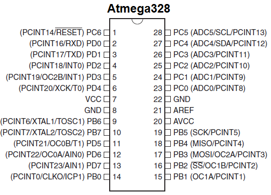
This a top view BTW.
The pin 5 test on the ATMega sounds like its worth pursuing, which one is it?
Bill
The first image that google came up with;
This a top view BTW.
So I skimmed through the thread a bit in attempt to get a grasp of what you have going on, ended up more confused! LOL
First of all I guess I should ask if you've cured the problem where the rPi reboots when you plug in your fan/damper? That is how we started...
Then I see you have some issues with the blower circuit and some odd voltage readings in that area, and your initial voltages seem to be the opposite of what you have now...
With all that in mind, I think we are on the right coarse here with the Pin5 test, that will tell us if it a problem in the blower driver circuit or something more systemic going on with the HM, because it will isolate the ATMega pin that controls the blower so we can see if it is doing what it is expected to do... From there we can either work through the blower circuit or work through the config settings or whatever may be screwing up the logic here. From time to time, particularly when a HM has problems on the first boot, an ATMega will get a bad flash and something will just be haywire...
Bill, are you the guy that had to replace the BS170 at Q1 with an NTE equivalent? Q2 is a BS170 that just drives the buzzer, so you can always steal Q2 and put it in the Q1 spot if you suspect the transistor you are using in the Q1 spot is bad. (Q2 is beside the buzzer)
If you do end up pulling Q1, while it is removed take the opportunity to check the voltage on the hole where the top pin would go. It should read just like PIN5 did on the ATMega when you had it pulled from the socket....
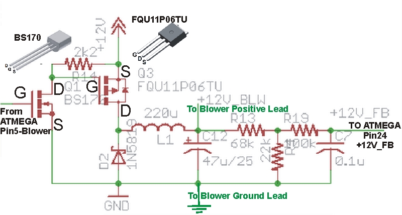
This is the blower circuit with some notes added. Everything to the right of where it says "To Blower Positive Lead" is the feedback circuit, which is not required when the HM is in PULSE mode. Again, Q1, Q3, R14, D2, these are the items I would focus on, and anything that could short out a trace that connects to these components.
Update: Got my Mouser order today and have replaced the 68k resister I lost in my carpet. I also removed Q1 and tested its switching functionality. I found a video on youtube that showed me how. I wasn't able to test its current delivery since I don't have a breadboard or other parts/pieces for that kind of test. With Q1 removed i re ran some of the aforementioned tests. Blower @ 0% I get 0v on center contact of Q1. Left is ground, Right 12v. Blower @ 100% I get 3.3v on center pin, 12v on right. So Im not sure if I'm getting 12v on the right most pin because the bs170 is not installed or if thats a function of the other circuitry. Q3, with Q1 removed, blower @ 0% seems to test the same as ever. Left 12v, center .85v, right 12v. I get the same readings on Q3 with blower @100%. Bad mosfet-p? Is there a way to test that? If I remove the misfit-p in Q3, and re-test the voltages at its pin locations should I see 12v,0v,12 @0% fan and 0v,12v,12v @100%?
I appreciate the circuit diagram above. However, at this time, my skills are not up to the level required to use it effectively. I'm kinda confused on one thing, should I be running these test with the blower set to voltage or pulse mode? I've been testing in voltage mode.
First, are you saying "left" and "right" pins as looking from the top of the heatermeter (with all the components on the other side)? Because BS170 placement (with no part installed) from the component side should read 12V 0V 0V at 0% and 12V 3.3V 0V at 100% so it sounds like you're reading them reversed so I am going to assume you've got it flipped over. I would think that the center pin would read closer to 0V. On my heatermeter it runs about 0.080V but quickly dissipates down to 0.010V. This charge comes from the electrochemical reation in the capacitor remembering having a charge but is quickly drained through the impedance of the multimeter. If you're getting 0.85V there, it seems current is leaking into that part of the circuit from somewhere, potentially through Q3.
If you remove Q3 yes you should see 12V 0V 12V at 0% and ~0V 12V 12V at 100% (with Q1 installed) or 12V 0V 12V at 100% (without Q1 installed). You should be able to run the tests in either mode, but the 100% value will be slightly different in pulse vs voltage. I think I measured 10.5V on the Q5 gate at 100% with no blower attached. Pulse mode should be ~0V at Q5 gate with nothing attached.
I suggest you do the testing with the HM in PULSE Mode, in Voltage mode the readings can kinda float a bit (particularly when no blower is attached). It seems your control voltage for Q1 is responding as expected, so that's a good thing. Personally I would put a new/different BS170 in the Q1 spot and resolder R14 on BOTH sides of the board (I had one HM blower circuit trouble me and it turned out no matter how many times I soldered R14 from the solder side it did not make the connection on the component side of the board). If that doesn't fix things then perhaps you might want to give Q3 a look, or swap it out... and give D2 a close check as well.
Bryan, yes, he is reading the voltages on Q1 from the solder side of the board, where the left pin is ground...
I've never personally measured voltages on the Q3 spot when the transistor is removed so I can't really say if that tiny bit of voltage is normal. That said, it is a TINY bit of voltage (0.146V), not like a dead short to 12v or anything, could just be some residual charge from the electrolytic capacitors? As for the floating voltage I referred to, that would be when the transistors were installed, I don't think you would see this with these two transistors removed... but the blower circuit is easier to decipher in Pulse mode in my experience.
At any rate, what I would do next is install Q1 and then measure the output voltage (on the right pin) at 0% and 100% and also measure the left pin of Q3 when you do this (it should read the same as the right pin of Q1). If you are getting a voltage ranging from 0V to roughly 12V then the Q1 part of the circuit is working. At this point I would install the new Q3 and test with the blower connected, see if you get proper control. When you install Q3 there is no need to solder the back tab to the HM board, skip that, it only increases the likelihood that you will damage the transistor.
Good luck! Post back your findings if you need additional help and I will try to respond ASAP so we can get this done once and for all so you can move on to the fun part of BBQing!
PS Since you said you had a rough go removing the transistors, before you install the new ones you might poke around with your meter in continuity mode, test the connection between each hole where the transistors go and the next component they connect to for continuity, test adjacent holes on the transistors for shorts.... Just to make sure you didn't break a trace or cause a short while removing the transistors... (do this without power connected to your HM board of coarse)

OK, that's progress, Q1 is doing what it is supposed to...
When you measured the center pin of Q3 did you have the Q3 transistor installed or not? You wont see the expected voltage there unless Q3 is installed. Since the proper control voltage is now being applied to the left pin of Q3 and the supply voltage is applied to the right pin, the center pin should be responding as expected and going from no volts to 12v when the HM goes from 0% to 100%...