Finished soldering, lcd has black row of squares...


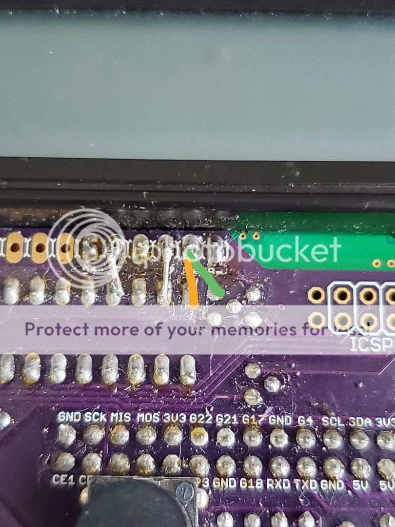
Ok, well that fixed the backlight that I didn't know was an issue :) Unfortunately, still have the black square. I checked continuity on front and back of display and all is good. Is there another spot that controls the display signal? I'm wondering if I tweaked something when I put it in the case.
 
The display signal is all of the green lines that Ralph highlighted on the schematic. You can check the lines on the left side by powering up the heatermeter, all the LEDs should blink once in unison. If they all blink, the lines going TO the shift register are good, if only one blinks, then you've got a problem on that left side (of the schematic). If they do blink then you've got a problem on the right side, the lines going from the shift register to the LCD.

Check from the shift register pin numbers from the schematic going to the LCD. Check them at the top of the LCD where you haven't soldered yet.
 
Trying to tackle this issue again. My LEDs blink once when power on. I have continuity on all the green lines on the right of Ralph's schematic. In checking continuity, I noticed that I was getting a strong signal via the orange line and also the correct green line. Could this be the issue? If so, don't see how they are connected.

20190625_131557_zpsqgtkdh2o.jpg
 
It should not be. The orange line is GND on the shift register and the green line is +5V for the LCD backlight. If they were really connected then your HeaterMeter would reboot continuously or just power off as the voltage regulator's overcurrent protection kicked in. Is it possible that when you're testing it, it starts off with continuity then shows not connected? If the system is completely devoid of power, then they would show connected for an instant as the test voltage shoots through the 5V rail's capacitor. Once it has a teensy bit of charge in it, the resistance goes up and it will then show as higher and higher resistance.

Did you check the other pins as well? Pin 2 goes to RS on the LCD, Pin 3 to E and the W on the LCD goes to GND.
 
Thankfully it does not reboot continuous, my only issue is with the LCD not showing characters - only black squares.

Pin 2 goes to RS on the LCD, Pin 3 to E and the W on the LCD goes to GND.
All these pins check out fine.


Back
Top