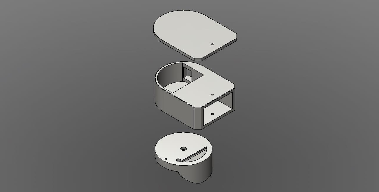
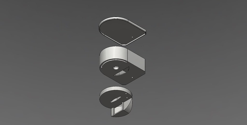
Servo / Damper pictures


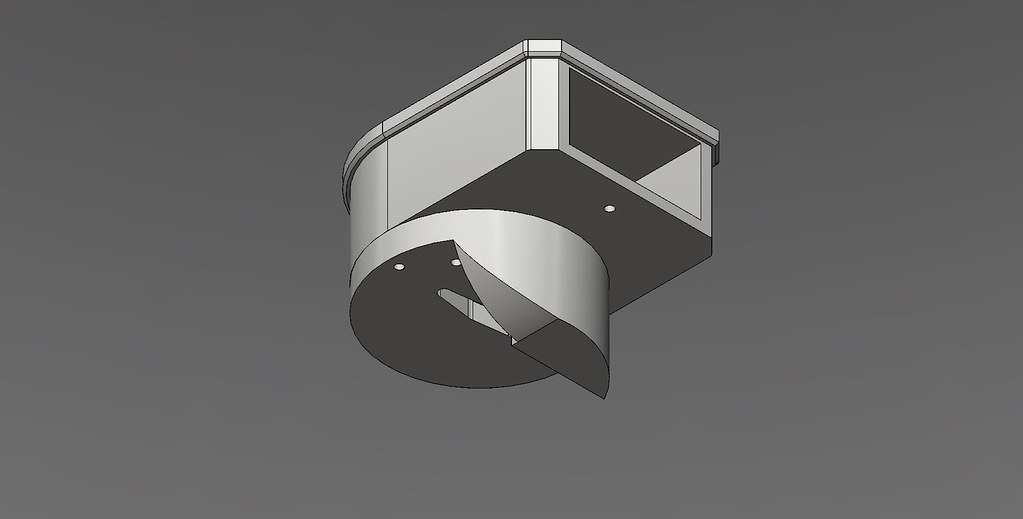
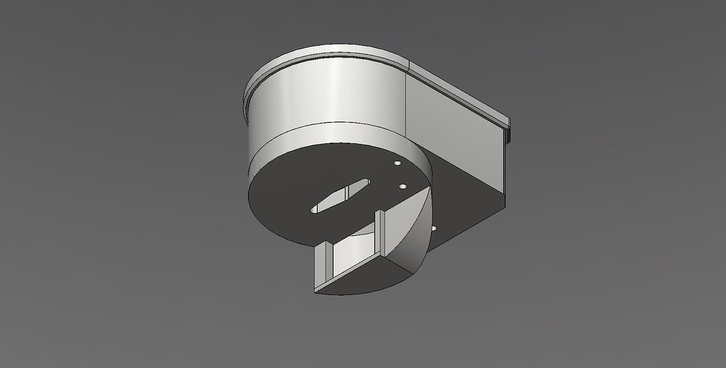
I got at least to the usable state with my design. Goals were to hopefully allow more airflow when the blower is off and the damper is open. To that end I've made a large exit area to reduce restriction. Another goal is to be 60mm tall (blower height) and under 2" wide (to make it easier to slide onto the BGE). The blower is also designed to be removable.
Profile


Closed


Open


Fan removed


I'd like to integrate the RJ11 jack, but I'm not sure I like this shape. I might change it to have the servo on the side, make the exhaust taller but thinner.
 
Looks nice. Why not just use the fan and servo together instead of fan only at max mode? Then you don't have to worry about the intake restriction.
 
My latest entry into the servo damper ring...
The Roto Damper:
RotoDamper+HM.jpg


A simple two piece 3D printed design.
RotoDamperOpened.jpg


Here's a short video if it in action.

I posted more details about in it in this thread here.
 
For those running ceramic egg/kamado style cookers, have you established a baseline BPID to be used with the servo driven damper? Still trying to get my head around BPID tuning.

Could you show a little more detail on how you adapted the pipe to the inlet? I've got a Kamado Joe too.

Thanks,
 
Linear actuator comes to mind, it could certainly apply enough force. Basically a 12V dc motor screw drive. Not cheap, however, $75 for this one, and then you need a way to control it, such as a linear encoder or some other closed loop sensing system. By default they basically open fully and close fully.

The servo is cheaper and simpler to control, IMO.

I'm looking at to how I mount it to my egg. I'm thinking that with the egg I might be able to keep the metal attachment piece small and leave the original sheet metal in place so I can open it wider for hotter temps and then have the servo do the fine control work for me. I'm surprised you are only getting 250 with PVC though. I haven't added mine yet but with a 1/16 to 1/8 inch crack in the bottom vent I can keep 225+. I would have thought 1.5" pvc would have been even greater.

Maybe we could make the the servo control the OEM egg air intake vent? That would give you the full air intake range and the fine control. I'm thinking make a mount that attaches to the two screws on the right so we count mount the servo to a bracket and then push/pull the original intake.
 
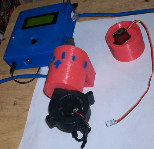
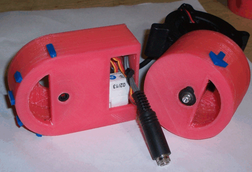
I designed this based on the rotary valve concept and a idea that Bryan had started but I think he abandoned along the way. My goals were to have a physically attached blower with completely separate air ducts and motorized components, a wider opening at the blower inlet, and to make it so that I could mostly shield the electrical parts from the weather since it seems to rain every time I bbq. This is what I got:

12150983415_688279bcd6_b.jpg


12150961975_abe3ef22e4_b.jpg


12150961945_5452a98da4_b.jpg


12150961895_fb4792335d_o.jpg


12151217463_66c62a9a2d_b.jpg


It prints in 3 pieces without any supports. The cover piece pops on and can be secured along with the rest of the unit to the 2" x 1" square tube that attaches to the smoker. The cover doesn't actually play any role in sealing the air ducts, it's just there to keep water out of the electrical/mechanical chamber.

Here is the graph of my torture test. Bear in mind that there is no food on the smoker which could alter the response times.

12151627096_1dc8f236a1_b.jpg


Large BGE
B: 0
P: 3
I: 0.008
D: 5
min fan: 10%
max fan: 100%
both fan and servo on

Anyone with access to a 3D printer that wants to try it, here are the files. The raw files were created in Inventor fusion and I also put up the corrected .stl files.

EDIT: I almost forgot. I am using a different blower than the stock blower. I found a smaller footprint blower on digikey that matched the original blower in static pressure, airflow, and current draw:

http://www.digikey.com/product-search/en?x=0&y=0&lang=en&site=us&KeyWords=603-1370-ND

I couldn't find it's 2-wire version so I just cut off the tach wire.
 
Last edited:
I designed this based on the rotary valve concept and a idea that Bryan had started but I think he abandoned along the way. My goals were to have a physically attached blower with completely separate air ducts and motorized components, a wider opening at the blower inlet, and to make it so that I could mostly shield the electrical parts from the weather since it seems to rain every time I bbq. This is what I got:

Tom, that's a very slick design. I love how low profile it is and the fact that you get to see the position that the damper is in. Does the servo struggle at all with moving the entire bottom piece?
 
Tom, that's a very slick design. I love how low profile it is and the fact that you get to see the position that the damper is in. Does the servo struggle at all with moving the entire bottom piece?

Not as far as I can tell, it's pretty light. The design is just a combo of Ralph's valve and Bryan's non-coaxial concept. I just wanted something that I could be certain wasn't going to fall off if it got knocked into and could operate in the rain because my bbq team has a couple of contests coming up and I was charged with fitting fan/servos to all of our smokers.
 
First off, thanks for all of the work on this. I'm just waiting on my v4.1 PCB and I'll be able to start construction of my HM and fan/damper. I have a few questions.

1) As I read it, the HM fan/damper will first cycle the damper from 0-100% open and THEN the fan come on? The fan then runs @ 100% (or is it also variable depending on needs)
2) As I review the multiple servo damper configurations I'm getting a little confused on design. If I use the spec'd HM fan from Bryan's cut list the limiting orifice on airflow is the exit of the fan. I'm planning on putting a servo controlled butterfly valve inside 1"x1" square aluminum tubing. I can step up to larger tubing but I'm not sure how it helps.

Thanks,

Rob
 
Rob,

The servo / damper config can be set in many different configurations.

ie:

servo and fan are both variable between 0 and 100%
servo moves variable from 0-100%, fan only comes on when servo hits 100%
servo toggles only between fully open and fully closed and the fan can run variable from 0 to 100%

There's many more config combinations to this as well.

Edit: All options are explained here:

http://tvwbb.com/showthread.php?49143-Wiki-update-for-fan-output-paraemeters
 
Last edited:
First off, thanks for all of the work on this. I'm just waiting on my v4.1 PCB and I'll be able to start construction of my HM and fan/damper. I have a few questions.

1) As I read it, the HM fan/damper will first cycle the damper from 0-100% open and THEN the fan come on? The fan then runs @ 100% (or is it also variable depending on needs)
2) As I review the multiple servo damper configurations I'm getting a little confused on design. If I use the spec'd HM fan from Bryan's cut list the limiting orifice on airflow is the exit of the fan. I'm planning on putting a servo controlled butterfly valve inside 1"x1" square aluminum tubing. I can step up to larger tubing but I'm not sure how it helps.

Thanks,

Rob

Yes, the cross-sectional area of the blower inlet/outlet will be the limiting factor for passive flow if it is smaller than that of the tube, with some addition due to resistance of the tubing. For forced air from the fan, the length and cross-sectional area of the tube will determine the pressure drop across the device and velocity of the air moving into the smoker.

I use 2"x1" rectangular tube because my blower outlet is about 400 mm2. 1" square tubing with 1/8" walls is about 360 mm2. I didn't want my tubing to have a smaller cross section than the blower so the next step up I had available was 2"x1". At almost 850 mm2 it's a bit of overkill but it doesn't add much to the mount for my smoker so it's not a problem for me.
 
Last edited:
Steve, what I want to do is have the servo cycle 0-100% without the fan running. The fan will run 0-100% only with the servo @ 100%. Can this be accomplished?
 
Steve, what I want to do is have the servo cycle 0-100% without the fan running. The fan will run 0-100% only with the servo @ 100%. Can this be accomplished?

If I interpret this correctly, you want the servo to come on from 0-100% and once the servo hits 100%, you want the fan to act as a second stage, going from 0-100%, which isn't currently an option.

Currently, you can have the fan come on when the servo is at 100%, but the fan will also come on at 100%, however you can control the max fan speed inside of the HM Config screen.

Yes, that's what I'd like to have in what I would consider a "ideal" set up. What configuration have you find works the best for bbq at low temps (250F) for long times (10+ hrs)?
 
I'm currently using a copy of the servo driven rotary style valve that Tom designed here. Both the servo and fan are moving from 0-100% at the same time. I'm able to sustain 15+ hours at 225F with it.
 
Any experience with Tom's design for high temp kamado cooking?

I'm currently using a copy of the servo driven rotary style valve that Tom designed here. Both the servo and fan are moving from 0-100% at the same time. I'm able to sustain 15+ hours at 225F with it.

Have you (or anyone?) used this design on a kamado type cooker at high temps, say 600-650 degrees? I love the simple, compact design and the vast majority of my need is for low & slow. But just wondering if the fan & fully open damper can crank up the heat quickly for pizza or steak occasionally. Not sure if 6.5CFM is enough oomph or not. Thanks.
 
I've never attempted to take it that high because I don't have a probe that could stand that temp. This will change when the TC board is out.
 
With the rotary style damper attached to my kamado joe, I changed the setpoint from 225 to 400 and held that for about an hour. One thing I did notice is that the plastic had slightly warped from the heat. The warping looks to have followed the contour of the mounting plate I made. Based on this, I think the damper would probably do a good job with higher heat cooks, but I'd want to greatly increase the distance between the 3D printed housing and the bottom vent.


Back
Top