New Build - Solder bridges, or by design?


Mark Swift

TVWBB Member
Howdy all,

I've just completed my Heatermeter build and was checking it over while I await my Pi & Probes...

Firstly, that was actually quite fun, albeit I couldn't find the right type k plug here in the UK (Hence the dodgy workaround for now, will that even work!?), nor did I estimate the substantial cost of a complete build, wow, I'm sure it'll be worth it!

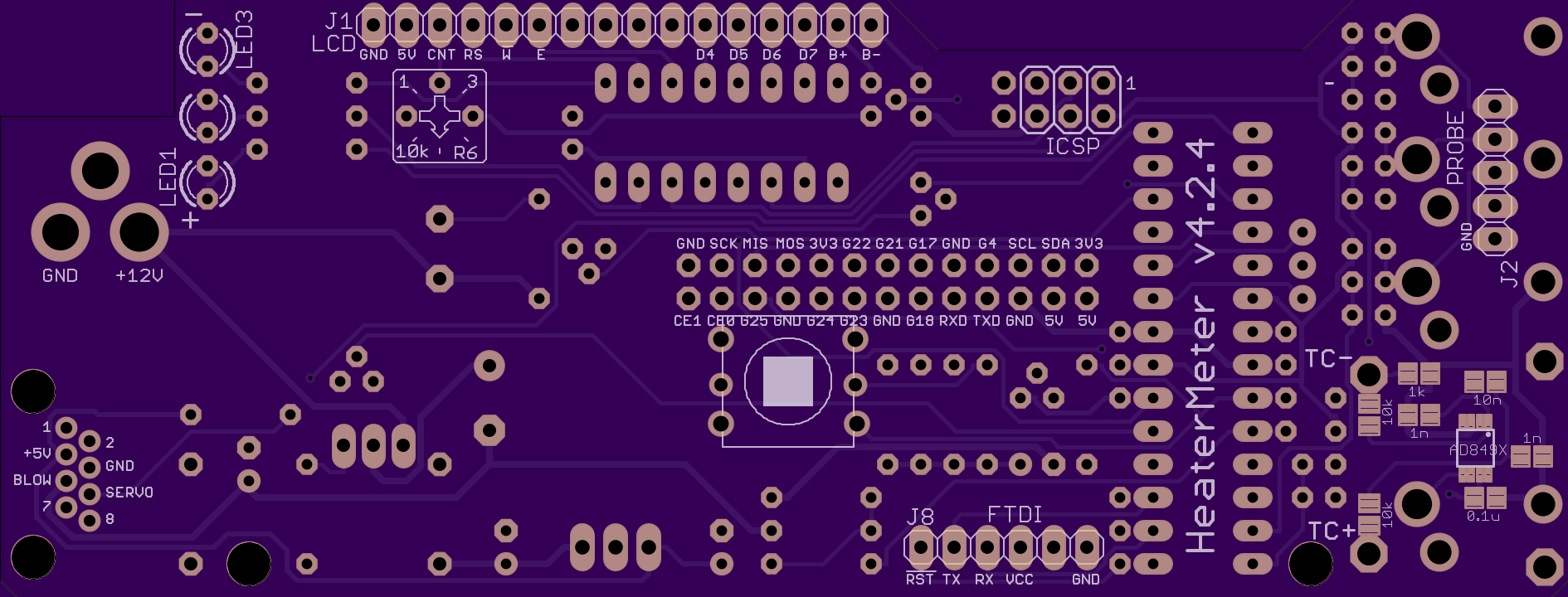
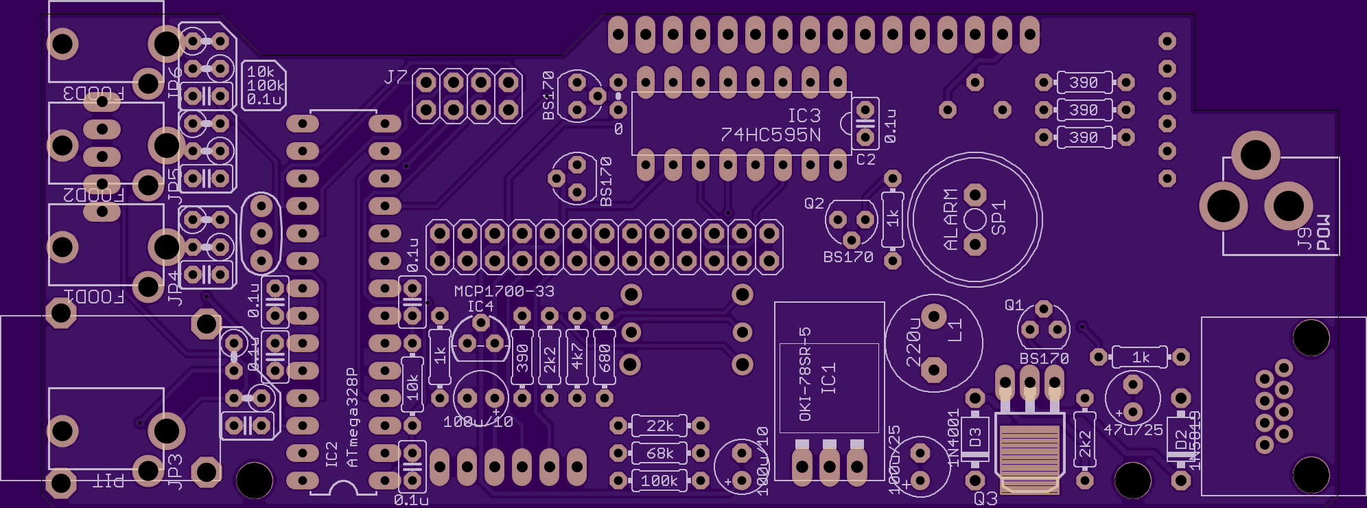
I've attached some pictures of the areas I'm concerned about. Given the proximity of the GND and various components I'm presuming it's by design as it's virtually impossible to avoid - I've highlighted the areas in question. Can someone help clarify, is this is okay?

http://postimg.org/image/pnmuq57hb/

Hoping they are okay, as it turned out pretty good otherwise.

http://postimg.org/image/9fld04rjn/

Thank you in advance for any help,

Mark
 
Last edited:
I just finished my build last night and had the same concerns at first, but mine seems to be working fine so I think it is by design.

And I hear you about underestimating the cost. What drew me to this project was that I had always wanted a CyberQ controller from bbqguru.com, because I wanted to be able to check in on my temperatures via my phone while away from the house. But at $400 it just didn't seem like a good idea. Now that I'm knee deep in my HM, I'm thinking I didn't save quite as much money as I expected. But I don't regret it one bit and fully expect to have a better product in the end than what I originally wanted.
 
Hi Chris,

Thank you for the reassurances, I sat looking at them for a while and was mildly tempted to try and reflow them!

Yes, the costs escalated quickly, PCB, components, 3D printed parts, barrel damper, probes, air burner, etc etc! I'm sure it will all be worth the effort.
 
If you look at the board before you solder it up, those areas in question are juctions where the two components are connected together so it is OK for the solder to bleed from one to the other.....
If concerned take a look at these images of the board from OSHPARK, you can see the traces here without components soldered to them and reassure yourself these things should be connected together

HMV4.2.4Top.png


HMv4.2.4Bottom.png


EDIT
If you cant see the area in question right click and save the image on your computer and then use a picture viewer to zoom in on the area in question.
 
btw, you did an exceptionally neat job soldering up your board, nice work!

Hi Ralph,

That really helps, thank you. I thought I'd seen a schematic somewhere but couldn't locate it when needed...

Regarding the solder job, until a year ago I was pretty much useless - I can thank the MANY late nights soldering my first APM Quadcopter for the improvement...

Can't wait for the Pi / Probes to arrive tomorrow; like a kid at christmas!

Cheers,

Mark
 
This gets asked so much I just added it to the assembly instructions. I'll agree your board looks so nice that I even used your picture (hosted on the HeaterMeter album). If that's not OK let me know and I'll take it down.
 
This gets asked so much I just added it to the assembly instructions. I'll agree your board looks so nice that I even used your picture (hosted on the HeaterMeter album). If that's not OK let me know and I'll take it down.

I'm honoured... I might even reflow the 2 terrible TC joints (They are like that because I had to workaround another K connector with wire bridges and glue!) and send you some better pictures ;-)


Back
Top