New HM 4.2 Build Questions - so far so good (I think)


Dave Pasma

TVWBB Member
Well I have the PCB kit (T/C), a power supply, an Rpi A, and a wireless adapter.

I have been following the assembly instructions on the wiki page. Thanks Bryan. Well done.

I just finished installing the connector jacks. I think I am getting close to the display installation.

I have been checking components prior to installing them, and checking the circuit values as much as I can practically.

I am thinking that I would like to power up the board and check for proper voltages as much as possible - as soon as I can , to avoid damaging sensitive components.

Is it a good idea if I power up the board prior to installing the display? I have the schematic, and I have enough experience to be able to find locations on the board and check for proper voltage.

Speaking of the schematic, I have Rev 4.2 (6/28/14). Is that the correct one for my "4.2.4" HM?

In operation, I think I have determined that the HM will work on its own. If I want to use a computer to monitor a cook, I will need wi-fi? Since i will use an Rpi A, I absolutely need wi-fi because there is no wired ethernet? If I take the HM on the road (perhaps to show off at a reunion), I will need wi-fi wherever I use it if I want to connect with a laptop?

Thanks
 
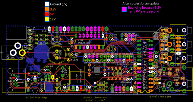
You can check the voltages without the Pi or LCD installed but many won't have their true values until after the AVR is programmed and up and running. I'm not sure if you've see the voltage check board image


The 6/8/14 schematic is the "v4.2.4" version yes.

You can hook the HeaterMeter up directly to a computer using an "FTDI cable" (USB Serial), however if you're also plugging in +12V you need to make sure the FTDI cable doesn't try to power the HeaterMeter board. You're also only going to get the the raw data, not the graphs or anything:
Code:
$HMSU,60,60.9,60.3,U,U,0,0,0,0*23
$HMAR,0,0,0,0,1,2*15

The HeaterMeter wifi can be used away from home if you switch it to AP mode, so then you'd connect to it directly rather than just being on the same network as it.
 
Thank-you very much Bryan. If you don't think there is some reason not to, I am going to power up the HM PCBA before proceeding and check for 12v, 5v, and 3.3v.
 
You'd have to do something pretty catastrophic to damage the display, so there's no harm in connecting the display prior to testing.

You won't receive any data out of the HeaterMeter until the Atmega328 chip has been flashed. This requires the HM board to be married up to the Raspberry Pi in order to flash the heatermeter firmware onto it. If you want to err on the side of caution, you can power the board via the 5v micro usb jack on the Raspberry Pi and then once the Atmega328 has been flashed, power it down, remove the Raspberry Pi and the commence with testing just the HM board being powered by the 12v supply.

Make sure you only ever power the HM via a single power source, either via the Raspberry Pi or a 12v adapter, but never both at the same time, as that will cause all sorts of badness!
 
Last night I did some homework - read about installation of the display. Thank-you Steve_M for the feedback.

I think I need some clarification. I have an 18-pin pin header. I see that the display will use 12 of the pins (2 @ 1x6). That leaves 6 remaining. In the instructions, it says: "J1 (LCD), J2 (PROBE), J7 (ISCP), J8 (FTDI)".

What is "J2 (PROBE)"? I think it is underneath the probe jacks? Do I install anything there? Pictures of the display installation do not show anything on the PCB, on the opposite side of the probe jacks.

What is J7 (ISCP)? On the PCB, it looks like it is a 2x4 ?

What is J8 (FTDI)? On the PCB, it looks like a 1x6?
 
The rest of the pins are just extra. I get them in 36 pin segments because they cost the same if they're 20 pins or 36 pins and split them in half for the kits. You only need the two 1x6 for the LCD (or you can do all 16 if you feel like it). 18 pins means you can totally botch one of the 6 pin installs and still have enough to try again. Actually some people get 19 pins and some get 17 pins sometimes because counting to 18 a dozen times is hard. :/

The J2 probe is for people who don't want to use the integrated jacks, so they have a place to plug into.

The J7 ICSP is for people who aren't using a Pi, they'll need to use an ICSP to program the AVR.

The J8 FTDI is for people who also aren't using a Pi, it is the serial output you'd connect a USB serial cable to with the standard 6 pin cable.
 
Update of my build:

Last night I got brave and powered up my HM 4.2. I did this before prepping and installing the display. I used the board layout with voltages labelled as a guide. I probed all of them and they were good.

I prepped the display per the instructions and installed it. I used alligator clips on a soldering station to align the display to the HM board before soldering pins 1 and 16. That worked very well.

After installing the button and contrast pot, I clipped the RCA jack off the Rpi A board and connected it to the HM. Everything looks good to me - a first timer.

So I guess I am ready for software? I need to read up on that. I have a bunch of old experience with software development, but I really don't know how the Rpi-to-HM-to-wifi adapter system functions. I hope to learn as I go while trying not to do permanent damage.

I bought my Rpi used via Amazon. Should I do something to it separately to make sure it works - before mating it permamently to the HM?
 
There's nothing permanent about the connection between the Pi and the HeaterMeter, they slip right together or apart. You can always boot it up with a monitor and a keyboard attached and say "wifi-client NETWORKNAME PASSWORD" which will mean that it will be a wifi client as soon as you boot with the wifi dongle installed instead of the keyboard. That's would verify that anyway.
 
Thanks for the continued support. I know the Rpi-HM connection isn't "permanent". I am just a bit cautious I guess. I wouldn't like it if I fried something - especially if it is something I can check out first.

I have a 2GB micro-SD card with an adapter. Will that work in the Rpi, and is 2GB enough?

What function does the Rpi serve? I know it will have a Linux OS on it, and it will perform the intial programming of the AT-Mega prcessor on the HM PCBA. After that, will it just facilitate the communications via w-fi, or will it execute code that is part of the HM operation?

Will the AT-Mega processor run code that you wrote? Is it open-source? Can I modify the software - provided I learn the language, and have the development tools?
 
The RaspberryPi is what provides the icing on the cake :)

It provides:

- Web based config
- Web based cook graph
- Ability to remotely set & change target temp
- Email & SMS alerts

Without the raspi married to the board, the heatermeter will still be able to control a cook, you just lose the ability to remotely monitor and manage it.

All of the code is available at https://github.com/CapnBry/HeaterMeter/
 
The Pi adds the wifi capability in a way that "Arduino Wifi" addons can not, as well as stores the graph data and generates all the dynamic content, notifications, etc. The HeaterMeter can control the BBQ on its own but it has no storage or ad-hoc query capability. It just spits out its data.

2GB is plenty of space. The image is, what, 32MB? I also slice off 64MB of storage for configuration backup and stash.

Everything is open source, and I've written all of it, from the ATMega source to the linkmeterd daemon source, to the web pages. OpenWrt, LuCI (web system), Flot, jQuery I did not write of course. You are free to do whatever you want with the source and you can build it all from scratch if you want.
 
Thanks guys.

I am having trouble getting my computer to use the adapted microSD disk. I may just pay the $10 for a full size SD card. The smallest I saw was 8GB. I just don't like the idea of having so much memory overkill - especially when I have a few 2GB micros. But, memory is cheap, so I think I'll get over it.

I kind of doubt that I will ever mess with the code. But it is nice to know that it is there and available.
 
I've had a lot harder time working with MicroSD cards than standard SD Cards too... Actually never had a problem with a standard SD card, but had problems with 2 out of 3 MicroSD cards I've tried. I eventually got all 3 working and not long after one of them locked down in write protect mode and stopped working. With the rPi + models you are locked into MicroSD, which I see as negative due to the above, if you have a non + model rPi I would recommend you just go with a full sized SD card if possible... 8G is like $5 on Amazon...
 
I read in the wiki: "For the first boot, using the rPi USB power input is preferred to verify the operation of your assembled HeaterMeter board without the chance of subjecting the rPi to 12V which will definitely fry components on it. I know from experience."

Since the power is entering the rPi, does it then send 5v to the HM PCBA? If I verified +5v at pins 24, 26 of JP1 when I powered up the HM (with just a 12v supply, no rPi), would that mean it is safe to power the rPi off the HM board?

Looking at the schematic, it looks like the HM will operate normally if power is provided to the rPi - except that there will not be 12v for the blower or the speaker? Everything else (incl the servo) will work?
 
Yes, everything besides the blower will work when powered through the rPi.... It used to be the HM sent 5v to the rPi and the rPi sent 3.3v back to the HM, so the onboard HM 3.3v reg was optional when running a rPi.... On recent versions of the HM that has changed and the onboard 3.3v reg is no longer optional, and looking at the schematic I see 5V on the rPi header but not 3.3v, so that must mean the rPi is now sharing 5v with the HM board (rather than 3.3v) and the HM is regulating it down to 3.3v....
I think the main reason to power from the rPi on first boot is to make sure you don't have something wrong on the HM board that will let 12V get to the rPi, 'cause that will kill the rPi QUICK and it has happened to more than one HM builder....
 
Ralph said it best but I'll elaborate on this a bit: The +12V from HeaterMeter powers the 5V Pi. Do not plug in 5V microsusb into the Pi *AND* 12V into the HeaterMeter because the two voltage regulators will fight, possibly to the death.
 
Thanks Ralph. You are validating that my schematic-reading skills were shelved for a long time, but not gone!

Well said Bryan, and I am pretty sure I wouldn't connect 2 supplies at the same time. But thanks for being my crossing guard.
 
Powered up - no smoke yet. Display says "Pit: 23 degF"

I prepared the SD card and I powered it up with the Rpi micro USB port. The display says "Pit: 23 degF [100%]". I haven't yet done any investigation. Is there something I could have done to the t/c circuit?
 
I prepared the SD card and I powered it up with the Rpi micro USB port. The display says "Pit: 23 degF [100%]". I haven't yet done any investigation. Is there something I could have done to the t/c circuit?

You just need to go to the web based config screen and change the probe type to thermocouple.


Back
Top