Heatermeter 4.2 problem Fuse error


BradShifflett

New member
I have built the heatermeter, but it is not flashing the chip. Booting up the device the Raspberry Pi is starting up, I am getting black squares on the LCD, but I have tried to run the AVRupdate and get the FUSE error I believe it is. Researching I found that to run tests with the multimeter, I am getting 3.3v and 5v at all contacts except this one, Pin 6 of the Pi header, not getting 3.3v, getting various readings, and then Pin 5 I believe it is on ICSP, according to the layout of the board, I should be getting 3.3v on both of these. Tracing these out, looks like they do interconnect on the Schematic. Any suggestions?

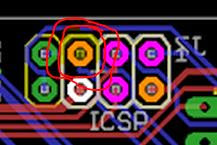
ICSP Red circled connector not measuring 3.3v
icsp-1.JPG


Raspberry Pi G25 connector not measuring 3.3v
pi-header.JPG


Im not sure where the short is, I have tested every resistor, voltage settings and the only ones are those two not getting correct readings. All the ones that say purple, should I be getting any readings from them yet? My understanding is those should only get a reading after it is successfully flashed.

If you need more info or photos, let me know. Hopefully I explained it well.

Brad
 
Yup you are well on your way to troubleshooting. You're right about the purple, those won't do anything until after you get past this avrupdate.

That pin, *must* be ~3.3V. It is the !RESET line for the microcontroller and if it isn't high, the ATmega never "boots". If you trace it back to Pin 1 of the microcontroller and it is 3.3V there, the short is on the RPi connector side. I'd test the circled pin on the ICSP header to see if the trace is shorting to any of the other pins on the RPi connector (do this test without the Pi connected). Without the Pi connected, there should be no conductivity to any of the other pins (besides G25 of course) and about 10k ohms to the 3.3V line I think.
 
Pin 1 on the ATmega is the bottom right correct? the pin closest to the Probe 4?

Excuse me for the dumb question, but how do I "test the circled pin on the ICSP header to see if the trace is shorting to any of the other pins on the RPi connector (do this test without the Pi connected)." Set the Multimeter to OHMs reading with no power to board, not have RPI plugged into Heatermeter? I have a cheap Digital meter, I believe it should say OL on the display and 10K on the G25 is what I am taking you are saying?
 
Looking from the top (the side with the LCD facing up) pin 1 on the ATmega is bottom left.

Set your multimeter to ohms, put one probe into the hole you circled on the ICSP header then go around with the other probe touching the other pins in the ICSP header and Pi header. They should be very high resistance to all but 3V3 (which should be around 10k I think) and G25 which should be 0 ohms. The resistance to pin 1 of the atmega should be 0 ohms as well.
 
did the tests and from the ICSP to the RPI I am getting 00.6 ohms. I tried checking from RPI G25 to ATmega and get OL on my reading, no Ohms readings, I put power into unit and I get 3.3V on the ATmega Pin 1. From ICSP to all other pins on RPI connector come up OL same as going to ATmega chip. So, thinking short between Rpi and ATmega and ICSP? ANy other things I can do to verify where the short may be? I need to get a magnifying class to check close to the board for shorts.
 
If you've got a smart phone or a half decent digital camera, take a picture of the front and back of the board and zoom in on them on your computer, you might be able to see the problem. You can also post them online and paste the links and we can have a look as well. Make sure they're as high a resolution as possible.


Back
Top