RJ45 Wiring


Alex_Seed

TVWBB Member
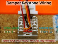
I am trying to build an adapt a damper and I have bought this RJ45 socket which does not have pin numbers but does have these colour codes on each side, it seems to give two alternative schemes, A and B. I would like to avoid connecting the 12V to the servo if possible :).

If I connect the heatermeter to this socket via a standard RJ45 cable which of these pins should I be connecting to the servo and fan?

UbC38dTorPBpBx0aIoWTXKeu_sAYSldocwammIx4L1YQuZJVwfbTDGsjDsHX-V8fUzL-1E5EzP7R2q2i0M6r1jjHdcD5Bo-hs9ft1j7j-kl9LM6gBjeXO7NJYeBb4j3cc7jMMjpNbgyy11OdTri6GWe5PxT95bATpX4Sqes-hrVm48x7QIHCL9Yf9OKIopZJyfpOj8D0C_GK_9Vl_OPSd1gTYSs_s7UyXCrGIS52GGhxExrHG3_0K31hvEp8X-25Q5eek4sjtPJBcehElshpcGrwEJxI0eZcAckZUMhCOXQ0RFoU9r8MQwPQXLQlSENSHJSliwJNJSysi97ETjmDOVLgW-8Jt-8pTnIHed5bra94izrzB6qf5xrygPjzZbmbM8IF4C_oaaEYnUGCBNcNMZMl4UoraFKg8ulC4sY5P2P_RIsX_kv8S9iD3Zh09m8RIcFigb8RRba47ks2POWs7_YtmFns0v2SCtpj9rdBL7TN0s0lkJPVvtf1TvD18mSGKIPRpgm2IZ1Vy2L-wmwSZHMgaYaxZ_D2XBQ-neJN-4vi5ZFqgVgPLQQAiQFqwFmOz_nCx4voqSlYs89eIGBMTb1OhkG4KujQEE6v5ssxo_On_HrdI8xTEenV8vQqXCSL3VvnQqbLxUWSw2ZKAdUoe3dncbu4IY6-9Ees7kCrCovQUe-aZUshsaoiiBW2YymgCld7KD6bzydOY_IwUc3pQqqk=w483-h643-no
foMxai3SQaUS1hxDZrS4x5h7QhCzW6N_aorITjv-auNDolBPB6YkvjxnXF6DrDf82bmzHlo2PxUYj2wkyjBG_CGkt_ppLXB5dujmWa5X61X-h11ICRag5WlLYIkL-v-WdJBB6GN_t1LosPDNls4jdHaj6CI0L9lr7dR_D_Ul0CEaIgCOnQWaBXxj4pHo_tiSe7S6bKoNFDCSFVhVoaTYR6rA5pveRaGUSGDOHuP8wMgy4eMMZdNOdxA31A5i8B1BervGjE2AdMKtG9CB4R68ryOvcZ7-aSDVuhnaqmyU0zccWXCukTRTbCcoA3anEqOr8265mEqDsldidKAkkM90vMFQrrgt-LZwiVwN9ru40dao-z5lZmmLbXqg-VG4KW2PL8bQcLb_ZqQEjxNam1W13nKUsSfmR_OzVBSv8QMhMB6jbZL9NFXPNWBeB33SEDgu41nL8uG-c6e6BMMtYWKGaHZ1DFp1gfAddQ18c1DU5Sy99ooaNF_5yI_vzrx6xf1mKOKZ30-Yi7UWq9nzdizsPpLh1RzcdNw7eIYZ46qFeVnbFFMJ5QLTpLi0SEMbUDKrrX6wtZdOEFagk3NQ8ctgviZlYSJ6GP32k2VgYQ5obfd4cd4fHbDKUxQoRBrs6CQDxPSfQeh11rTezXBdoLD0UczBVcvluTuZAHSVLcLxeeFVnFSOWgWGva7CcZwkFQnwlja7QSgD3DAQs3I7x_bdEBnl=w483-h643-no
 
Looking at the docs I should be using 568B but my connector doesn't match the numbers or position in the image from the docs, on my connector all of the indicated wires are all on one side of the connector.

I really wish that they had put numbers on the pins!

Any ideas?


1629060205426.png
 

Attachments

  • 1629060117838.png
    1629060117838.png
    1.2 MB · Views: 2
My keystones here were all different too. I solved it by putting the fan on 100%, and using a multimeter to check for where I had +12v and a ground. Try that?
 
<scratches head> I think that you do need to pay attention to the color coding, regardless of how it's made, they should be either EIA 568 A or EIA 568 B (the differences are where you have 2 colors on a contact.) On any EIA 568 B capable keystone, the orange/white labelled connection will connect to pin 1.

For anybody who's not ears deep in twisted pair Ethernet networking, the majority of cables are what's called straight through, and it really doesn't matter if they're wired to the A standard or the B standard. The connections on switches & computers are very specific to task, and you can't connect computer to computer with a straight through cable. A crossover cable, one end on A, and the other end on B, will allow you to connect 2 computers back to back without a switch or bridge in between.

If I have some time tonight, I'll dig out one of my old fan assemblies, and post up the EIA color codings on the connections I used.
 
The simple way to figure it out is to leave the HeaterMeter not powered and use continuity on the multimeter. Plug in the cable into both sides, the HeaterMeter and the jack, then just probe the HeaterMeter's labeled RJ45 connection and find the slot in the jack that makes it go beep. E.g. put one probe on where it is labeled "Servo" on the HeaterMeter, then poke the keystone with the other probe until it beeps and that's where the servo goes. Repeat for the other 3x pins.
 
<scratches head> I think that you do need to pay attention to the color coding, regardless of how it's made, they should be either EIA 568 A or EIA 568 B (the differences are where you have 2 colors on a contact.) On any EIA 568 B capable keystone, the orange/white labelled connection will connect to pin 1.

For anybody who's not ears deep in twisted pair Ethernet networking, the majority of cables are what's called straight through, and it really doesn't matter if they're wired to the A standard or the B standard. The connections on switches & computers are very specific to task, and you can't connect computer to computer with a straight through cable. A crossover cable, one end on A, and the other end on B, will allow you to connect 2 computers back to back without a switch or bridge in between.

If I have some time tonight, I'll dig out one of my old fan assemblies, and post up the EIA color codings on the connections I used.

It seems to be wired "oddly", I contacted the manufacturer and received this. am I right in thinking that that is "odd"?

1629132476438.png


1629132594287.png
 
Don't think that's odd at all. The A & B variants swap the orange & green pairs to allow for cross connection of Transmit & receive. The blue & brown wires stay the same. Those look like bog standard EIA568 wiring schemes, you punch down the wires depending on how you want this end configured.
 
It's just all on one side instead of being half and half like the reference image.

This is ridiculously simple and you're over-thinking it. Do the procedure I outlined above:
The simple way to figure it out is to leave the HeaterMeter not powered and use continuity on the multimeter. Plug in the cable into both sides, the HeaterMeter and the jack, then just probe the HeaterMeter's labeled RJ45 connection and find the slot in the jack that makes it go beep. E.g. put one probe on where it is labeled "Servo" on the HeaterMeter, then poke the keystone with the other probe until it beeps and that's where the servo goes. Repeat for the other 3x pins.

You don't have to know what pin number it is, or what color the wire is in the cable, or if it is A/B standard. When it beeps, you put that wire there.


Back
Top