RStanislav
New member
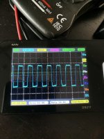
Hello! I have project based on Arduino mega where i integrated part of the schematic of heatermeter - fan voltage control part, i'm, using pin 8 of arduino to output PWM, i have checked that it has ~62khz freq and at almost 100% duty over 3.3 volts on pin

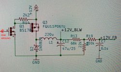
But for some unknown reason to me on left pin of BS170 i read about 300mv at 90% duty, and at 0% - 4,46 volts, that looks inverted and also doesnt affect fan speed at all - its constant, if i short left pin of FQU11(that has connected to left pin of bs170) with 12 volt line it drops fan speed to zero as expected, i have checked everything like 40 times, i even tried to manually put 3.3v to BS170 gate pin (center), replaced bs170, replaced FQU11, checked all resistors.. no result and i dont understand why its not working, can someone help me please ? Only difference from BOM is that i used https://eu.mouser.com/ProductDetail/EPCOS-TDK/B82477G4224M?qs=/kiEPUfD/qmEI2BmzVrHdw== L1 coil.
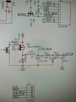
This is part of schematic i'm talking about:

Last edited:

