Help Display Not Working Right - V4.3


Tony S

New member
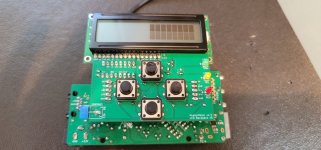
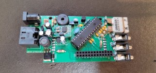
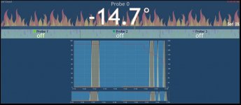
So I have my HM built, and it appears to be mostly functional, outside of the screen. The board connects to the internet, and all of the probes respond as expected. So I have used the HM to monitor a few cooks, but I haven't been able to get the screen functional enough to change any of the settings.

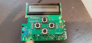
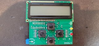
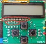
The screen shows up as the right half of the screen black blocks when I first boot it up. If I press the buttons it clearly is cycling through menus, and the blocks either disappear all together or switch to a single top row. I know that it is doing something because if I press buttons I can check the website and see the setpoints changing, or the lid off mode being activated. It feels like essentially everything is working outside of the screen being gibberish.

Sometimes the LED back light works and sometimes it doesn't. Today it was not working.
 

Attachments

  • 20210619_114309.jpg
    20210619_114309.jpg
    112.3 KB · Views: 5
  • 20210619_114321.jpg
    20210619_114321.jpg
    110.7 KB · Views: 3
  • 20210619_114417.jpg
    20210619_114417.jpg
    134.9 KB · Views: 4
  • 20210619_114423.jpg
    20210619_114423.jpg
    125.3 KB · Views: 4
  • 20210619_114432.jpg
    20210619_114432.jpg
    120.7 KB · Views: 5
  • Capture.JPG
    Capture.JPG
    54.6 KB · Views: 4
I'd suggest starting with figuring out why the backlight only works sometimes. That's a simple circuit where the pin from the atmega just comes up the riser pins through the "LBK" pin and goes directly to the BS170 mosfet that controls the backlight. Use a multimeter to trace it out and make sure it isn't connected to anything else. There are some diagrams to help see where the traces go here:

You can also trace out the LCD data pins to make sure they're connected to the pins of the shift register D0-D4, RS, E pins (and not connected to each other).

You can test the connection from the atmega to the shift register using the LEDs. Set the function of all of them to "Off" and "Inverted" (which is ON) in the webui and they should all light up. If only the RED comes on, there's a problem between the atmega and the shift register. If they all come on and turn off when you set them to "Off" (not inverted), your connection is good from the atmega and the problem is between the shift register and the LCD itself.

Also, your pit probe is -14.7? That doesn't seem right either. Make sure the probe type is set to "Thermocouple" with "5mV/C" and zero offset.
Ok, I got a few minutes to troubleshoot. I went into the configuration and found that the backlight was set to 0%, when I changed it to 100% it appears to be working now. I was blindly pressing the buttons to see if I could see any real response on the web UI, and I must have toggled that somehow.

For the LED testing, I was able to get all of them to turn on when I put them on Off Invert, and then all of them turned off when I switched it to Off.

The Thermocouple used to read something like -2.3F, but changed to -14.7 when I was button mashing, I presume that I messed up a setting there too that. Is -2.3F a more normal number when you don't have a probe connected?

For tracing the data pins, I apologize for my lack knowledge, but what do I actually need to do to trace them? I checked voltages on the main board and everything appeared fine, do I just find the circuit and confirm that the voltage from those pins makes it to the right spot on the LED board?
 
The Thermocouple used to read something like -2.3F, but changed to -14.7 when I was button mashing, I presume that I messed up a setting there too that. Is -2.3F a more normal number when you don't have a probe connected?

No, there should be no reading (Off) when there is no probe connected.

For tracing the data pins, I apologize for my lack knowledge, but what do I actually need to do to trace them? I checked voltages on the main board and everything appeared fine, do I just find the circuit and confirm that the voltage from those pins makes it to the right spot on the LED board?

To trace the data pins, you have the unit unpowered and use the multimeter's continuity check to verify that you have a connection from A to B, and anything adjacent to A doesn't show as connected to A, and anything adjacent to B doesn't show as connected to B. For example, check D5 on the shift register shows as connected to D5 on the LCD, but not to D4 or D6 on the shift register or D4 or D6 on the LCD.
 
No, there should be no reading (Off) when there is no probe connected.


To trace the data pins, you have the unit unpowered and use the multimeter's continuity check to verify that you have a connection from A to B, and anything adjacent to A doesn't show as connected to A, and anything adjacent to B doesn't show as connected to B. For example, check D5 on the shift register shows as connected to D5 on the LCD, but not to D4 or D6 on the shift register or D4 or D6 on the LCD.
Ok, so just to be sure I'm doing this right.. I checked continuity from the pins I installed on the bottom of the LED to the pads on the top of the LED?

I went through and checked all of them to see if they were connected to the corresponding ones above. RS, E, D4, D5, D6, and D7 were all good. B+ and CNT connected to more than one, but they aren't adjacent ones.

I also checked to be sure there was continuity from those pins on the SN74HC595N chip. I didn't notice anything wrong there either.

Once I updated the thermocouple probe to the right settings it now reads "off" as well.

I guess one other thing worth noting is that I was checking voltages at one point and randomly the screen started functioning normally. Once I unplugged it and plugged it back in it stopped working. I reflowed all the solders to see if it was just something loose, but it didn't fix it.
 
Ok, so just to be sure I'm doing this right.. I checked continuity from the pins I installed on the bottom of the LED to the pads on the top of the LED?
I'm guessing you meant LCD not LED? I meant just checking them from the pins labeled on the shift register to the pins labeled on the LCD connector.

B+ and CNT should not show as connected. B+ is 5V (they are both 5V I mean), but you said CNT was not connected to 5V, so maybe double check that connection to make sure CNT is not 5V/B+.

Did you check this too?
You can test the connection from the atmega to the shift register using the LEDs. Set the function of all of them to "Off" and "Inverted" (which is ON) in the webui and they should all light up. If only the RED comes on, there's a problem between the atmega and the shift register. If they all come on and turn off when you set them to "Off" (not inverted), your connection is good from the atmega and the problem is between the shift register and the LCD itself.
 
I'm guessing you meant LCD not LED? I meant just checking them from the pins labeled on the shift register to the pins labeled on the LCD connector.

B+ and CNT should not show as connected. B+ is 5V (they are both 5V I mean), but you said CNT was not connected to 5V, so maybe double check that connection to make sure CNT is not 5V/B+.

Did you check this too?
Ok, I think I might not be checking the right spots then. I attached a picture of the pins that I checked. I did the ones circled in red up to the pads circled in orange.

The B+ and CNT weren't connected to each other, just had continuity with more than one of the pads above. I just couldn't tell if that was supposed to be that way.

I did do the LED test and that worked correctly, all three turned on and all three turned off.

Thank you for all the help, this has been an elusive problem for me, and I'm a little out of my depth in electronic troubleshooting.
 

Attachments

  • Screenshot_20210624-110233_Photos.jpg
    Screenshot_20210624-110233_Photos.jpg
    687.5 KB · Views: 3
Ok, I think I might not be checking the right spots then. I attached a picture of the pins that I checked. I did the ones circled in red up to the pads circled in orange.

The B+ and CNT weren't connected to each other, just had continuity with more than one of the pads above. I just couldn't tell if that was supposed to be that way.

Ah I see. I meant the red pads to the other red pads. The orange at the top and the red at the bottom should be identical as they are just straight direct-connected copies of each other. What other pin did CNT appear to be connected to other than the same pin on the other side?


Back
Top