Designing an adapter for damper, looking for advice on location on Char-Broil Kamander


Juho A

TVWBB Member
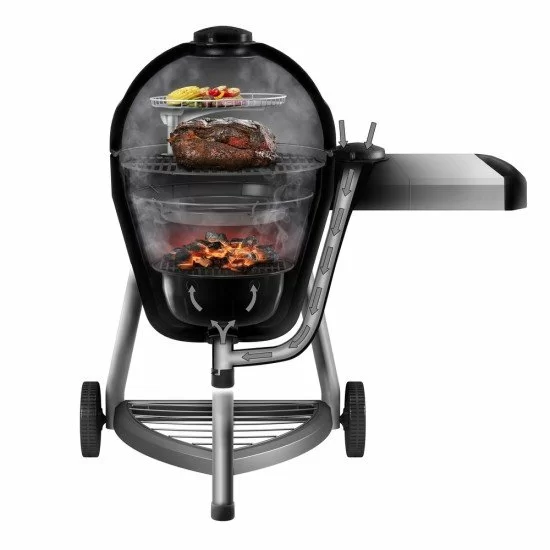
I'm starting to design an adapter to a damper design to fit on my new Char-Broil Kamander. The plan is to print it in PETG, and I will design it in Tinkercad. I am looking for advice / thoughts on where it would be best to attach the damper. The Kamander has a convenient location of the inlet valve on the side of the desk, shown with arrows here:
kamander-09-550x550.jpg.webp


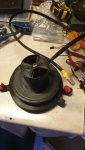
but there is also the "dust cap" in the pipe on the bottom, so it would be possible to locate the damper there, if there's any sense to do that. My primary choice however would be to put in on the desk where it's convenient, and make the adapter a big one to fully cover the inlet valve and make the design so that it locks the inlet valve fully open when it's inserted on there. I was thinking if I add some neodymium magnets and a bit of sealing tape, it could mount onto the inlet valve airtight. This is how the inlet valve looks close up, the inlet valve itself is cast iron, so no magnet holding that, but the magnets would attach to the steel its mounted on:
14832041.jpg


If that wouldn't work, the ash cap in the bottom is another option, I could design the adapter so that the ash wouldn't fall directly in the damper, but still I feel I would rather do the one on top instead, if there's no reason it wouldn't work:
14832042.jpg


Any reason it wouldn't work on the top of the table?
 
That's pretty cool, I've never seen that design before. I'd try to make something that sticks to the vent hole on the table. You could make a cylinder with one side cut out that is static and mounts with a magnet + some gasket material and inside the servo would just turn an inner shell that would open / close the hole. Then the HeaterMeter could just sit on top of that static cylinder.

That would work best with an axial fan though instead of a blower so it might be difficult to achieve the static pressure needed to force air through all the plumbing, but maybe you could add some stator vanes past the fan to increase the pressure. Oh man this is already getting too complicated.

Maybe something more like the Offset Rotary Valve except the air comes out the bottom instead of the side, and into that table vent.
 
Already did my first draft, actually printing a draft of the 4 pipes to check my measurements are correct

MicD-draft1-2.png


MicD-draft1.png

The upper and lower part would be merged together like this, but I am not sure if this would ever be printable... Perhaps I need to make it a few parts...
MicD-draft1-3.png
 
That's pretty cool, I've never seen that design before. I'd try to make something that sticks to the vent hole on the table. You could make a cylinder with one side cut out that is static and mounts with a magnet + some gasket material and inside the servo would just turn an inner shell that would open / close the hole. Then the HeaterMeter could just sit on top of that static cylinder.

That would work best with an axial fan though instead of a blower so it might be difficult to achieve the static pressure needed to force air through all the plumbing, but maybe you could add some stator vanes past the fan to increase the pressure. Oh man this is already getting too complicated.

Maybe something more like the Offset Rotary Valve except the air comes out the bottom instead of the side, and into that table vent.

Thanks Bryan. Airflow engineering is one of the long list of things that is not my strength. :D 
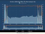
But I was kind of assuming that if the Kamander gets sufficient air from that plumbing with that inlet valve, then same principles would apply for adjusting the airflow as with any other pit, and thus I could choose any damper design that would work with a kamado-style pit. Honestly didn't think about the plumbing adding another layer there, but it very well might. The damper I decided to go with initially was the microdamper, and I ordered the parts recommended for it, but I wonder if that little 40mm fan is going to be sufficient for this after all. :oops:
 
Wowie wow wow what a great idea to use the existing MicroDamper top and just design a new bottom half for it. Brilliant!

I'm not sure if you'll need the bottom half of your bottom half, since it would just add a teeny bit more constriction to the airflow. Just mount 4 magnets around the rim of the upper bit and maybe a bit of gasket internal or external to that rim. I'm also sending you a PM with an additional idea.
 
I agree with Brian with using the Offset Rotary Valve. The tighter the seal of the grill, the more pressure you need to move air. When grill is the coldest, with a tightly sealed grill, the air pressure is highest. Air density drops as it gets warmer. But with that long snorkel air feed, which is a cool idea, the air will probably stay dense until it finally get in the grill. Second is, The Tom Kole Offset Rotary Valve design works great. I use it along with a Adapt-A-Damper for my small Primo jr. Looking at the RD3 damper, that would work as well. What I have learned over the last few years and trying all the dampers found on this site except the RD3 damper, is that for tightly sealed grills, a blower style damper works best and also do not oversize the damperand fan. We use axial fans for computer cooling because the cooling surface is usually not sealed tight so there is no resitance to the flow of air. When the area, or room is sealed, blower can develope the pressure to move air. Furnace fan is a good example. Last thing to remember is larger, damper size and fan flow output, does not mean best performance. Here is the graph of my last cook using a Tom Kole Offset Rotary Valve. Nice day in upper 60`s to low 70`s. Low humidity as well.
 

Attachments

  • ribs TK offset damper.jpg
    ribs TK offset damper.jpg
    79.9 KB · Views: 7
Thanks guys, I think Bryan is spot on with scrapping the extra part in between - even if I managed to design it fully unrestrictive in terms of airflow per se, it would still reduce the size of the vent holes at least by a couple of millimeters (i.e. the thickness of my printed "pipes"). Plus it would be a difficult print. So, I will make the next iteration of the adapter so that it covers the vent completely.

Gary, I am still very new to the graphs shown by heatermeter, but I take it the red line is the pit temp sensor, the lighter surface area is the percentage of the damper opening, and the darker surface area is the percentage of fan speed? I cannot see the lower graph showing anything extra to that, is it just the same view "compressed"? I take it the "spikes" are you opening the grill?
 
Gary, I am still very new to the graphs shown by heatermeter, but I take it the red line is the pit temp sensor, the lighter surface area is the percentage of the damper opening, and the darker surface area is the percentage of fan speed? I cannot see the lower graph showing anything extra to that, is it just the same view "compressed"? I take it the "spikes" are you opening the grill?
The red line is the setpoint, the orange is the pit temperature. Then the servo is the white filled area, and the fan is the bluer filled area. The spikes with the yellow zones are when the lid was open. I think the takeaway is that the fan barely runs and the servo isn't even all the way open and it is maintaining the temperature so there's plenty of power / airflow available.
 
The red line is the setpoint, the orange is the pit temperature. Then the servo is the white filled area, and the fan is the bluer filled area. The spikes with the yellow zones are when the lid was open. I think the takeaway is that the fan barely runs and the servo isn't even all the way open and it is maintaining the temperature so there's plenty of power / airflow available.

Thanks for clarifying that for me Bryan. Based on the initial fan speed / damper opening, it looks like the fan can considerably help in the initial startup and heatup of the grill. (y)
 
20200510_192938.jpg
Allrightie, now the adapter piece is done. Just need to print the top part (just a flat circle with the microdamper bottom part embedded to it) and 3d pen it together, then design and print the magnet "wings", glue on the insulation and I am ready to roll once the servo and fan arrive. :)
 
Thanks Bryan! Its been interesting to tinker with this design for a couple of evenings. I might have everything but the servo already next week, as I decided to cancel the backorder items at mouser and ordered them from digikey. Maybe next weekend its time to fire up the weller. :)
 

14837881.jpg
14837880.jpg

Some progress, got it fitting snugly with the seal, and added the magnets to make sure it stays there. Got the fan from mouser, still waiting for the servos from ebay.
 
Last edited:
Wanted to make her mighty purrrdy too, so decided to design and print two pretty and functional parts. :D

14837942.jpg
 
:LOL: Love it! Hey if you aren't spending extra time making it look cool, then you're missing out. I made a little device yesterday I can bring with me to the living room when I am 3D printing at night to let me know when the printer finished. Spent only about 20 minutes putting it together, but have spent at least an hour trying to make it look fancier.
2020-05-15.jpg

My ladyfriend is really pushing for me to add some tiny dials and a pair of rabbit ear antenna.
 
Thanks Bryan. Is that ESP8266-based? Are you using octoprint? I used it with my first printer, but I didnt get it working right with my new one, I blame the SKR Mini board which is quite crap otherwise too. I really liked octoprint and would like to still use it, but as I had such huge issues getting my printer to work with the upgrades, I just havent wanted to risk my ability to print reliably by tweaking anything on the FW anymore.. :/
 
Very nice, both the original design and your addition. However, I'm predicting you'll be printing version 2 before long incorporating a radial fan, and perhaps a rather large one at that. You're going to have some flow losses in the long inlet tube as well as back pressure, something axial fans don't really like. A radial fan would be a better bet. Although only a tiny fan is needed to maintain temperature during a cook, I'm of the "more is better" school of design, figuring you can always throttle back on a large fan. I'm thinking of those days I'm trying to re-use a big batch of left over charcoal which has been sitting in the humid/damp weather for a long time. Sure you can use a leaf blower but I find it nice to just crank up my over sized fan and let 'er rip until the coals are nice and hot. Something to think about anyway.
 
Thanks Bob, you're probably right. I actually do have a box full of different types of fans, but for once I decided to go with tried and tested items, and get a feel for the system for those before starting to tweak. It's been a few too many times that I've decided to just dig some scrap parts out of the shelf and try to whip it together and then spend a ton of time troubleshooting. :) I'll do version 1 with these, and then start testing something else. Just started thinking if I'd also need to change the design to a bit angled one so that in case of rain it wouldn't be raining directly into the servo and fan. Didn't think of that before. :)
 
I finally soldered the cabling and put this together, as DHL's tracking says I might have my heatermeter tomorrow. Phew, it's certainly been an adventure so far. 😁
 

Attachments

  • 20200715_185716.jpg
    20200715_185716.jpg
    92.8 KB · Views: 20


Back
Top