Have I killed my new build


SpencerB

New member
I was trying to solder on the Thermo couple amp and in trying to reposition it I've pulled the top left (as you look at it) pad off the board.

Is there any way to recover from this or have I killed it? If I have killed it I assume I can continue with the rest of the board and use a probe instead of a thermo couple is that correct?

 
Yeah that's some good luck right there! You can just tell everyone that the pin was extra dead weight so you removed it to optimize the design.
 
How lucky am I??

upload image from url
Now I've got the middle pins on the top shorted together and can't for the life of me get rid of the solder in-between.

Have I massively underestimateaded the difficulty of the smd soldering or will this still work?
 
sweet!! are there instructions for the 4.3.4 board somewhere? the ones linked aren't quite the same as the board I have. (but I think I've got it right so far)
 
Last edited:
The 4.3.3 and the 4.3.4 are identical apart from a couple things being skooched around by a millimeter, two parts swapping position (D3 and 1K resistor), and one swapping orientation (D2). I did film a new assembly video but my dumb camera stops recording at 29 minutes (to avoid being a 'camcorder') so I only recorded the beginning and don't feel like setting it all up again considering how close the two are.

The schematics and board layout images are up to date though 434 Base and 433 Base if you want to flip back and forth between browser tabs to see the differences.
 
So I'm all built, only the display says - No Pit Probe - with or without the thermocouple connected (I've set it to thermo couple in the web interface). Is there anything simple to check? I've shorted the thermocouple inputs together and nothing happens but if I touch the board with my finger I get a reading (not sure exactly what I'm shorting to what when I do that).

if there's nothing simple to check is there a way to assign one of the other probe inputs to be the pit temp or do I need to try and remove the the thermocouple jack and solder on the 3.5mm input?

Or is there an off the shelf thermcouple amplifier I can buy that's compatible? a quick search on ebay suggests there's loads out there for as little as a couple of $ but I'm guessing nothing that will simply work in line.

Edit....
Think I found the issue I'd fitted the 10k resistor in the 100k holes it's now showing 41 degrees F when I plug the thermocouple in so it needs calibrating (temp is around 75 F )

So doesn't looks like it works :( I think the board was still hot from soldering) I've done something and it read a temp of 300 f then dropped slowly until it goes back to saying - No Pit Probe -
 
Last edited:
The Pit probe is actually defined as "the first non-Disabled probe in the list" so you can just set the type of Probe 0 to Disabled and it will start showing Probe 0 mirrored to the Pit probe.

Trace down and make sure you've got a good connection from the top left pin of the amplifier to the 10K resistor on TC-, then from the 10K resistor to TC- and TC- to the 1K resistor and the 1K resistor to GND. On the top right pin, it is from there to the 10K resistor on TC+, to TC+ and that's it. Make sure one side of the 10n capacitor is connected to one side of a 1n capacitor and nothing else, and the other side goes to the other 1n capacitor and nothing else. The remaining sides of the 1n capacitors go to GND. In essence, for every red line on the board image, make sure a multimeter says you have continuity between the things connected with the red lines and nothing else in the vicinity.

You can also check the voltage output at the big circle by the TC+ 10K resistor. It should be ~3.2V with nothing connected, then drop to ~150mV for room temperature when you short TC+ and TC- together.

I'm not sure what you mean by off the shelf thermocouple amp, but if you mean one that's already soldered to a board, you can use pretty much any of them with the latest snapshot, but you'll need to enter an offset for whatever voltage reference they use and you'll have reduced precision, ~33% of the precision of the stock HeaterMeter for temperatures below ~220C.
 
Looks like my smd soldering is all over the place, pins 2 and 3 go to ground and the 1 n capacitor is connected to more than just the 10 n capacitor.

But if I can just disable probe 1 and put probes in food 1 and food 3 (pit and meat) then I'm happy.

by off the shelf thermo couple amp I mean something like this

https://www.adafruit.com/product/3263

or

https://www.ebay.co.uk/itm/182601580106

or

https://www.ebay.co.uk/itm/283452720381

something like that that I could hook up via the J2 on the back of the board would be amazing.
 
Actually I should have been more clear when I said "top left" and "top right" thermocouple pins. I was referring to the amplifier pins as they would be if pin 1 was top left, not its installed orientation. I think I made it more confusing so let me try again. The key is to not listen to me ;) 
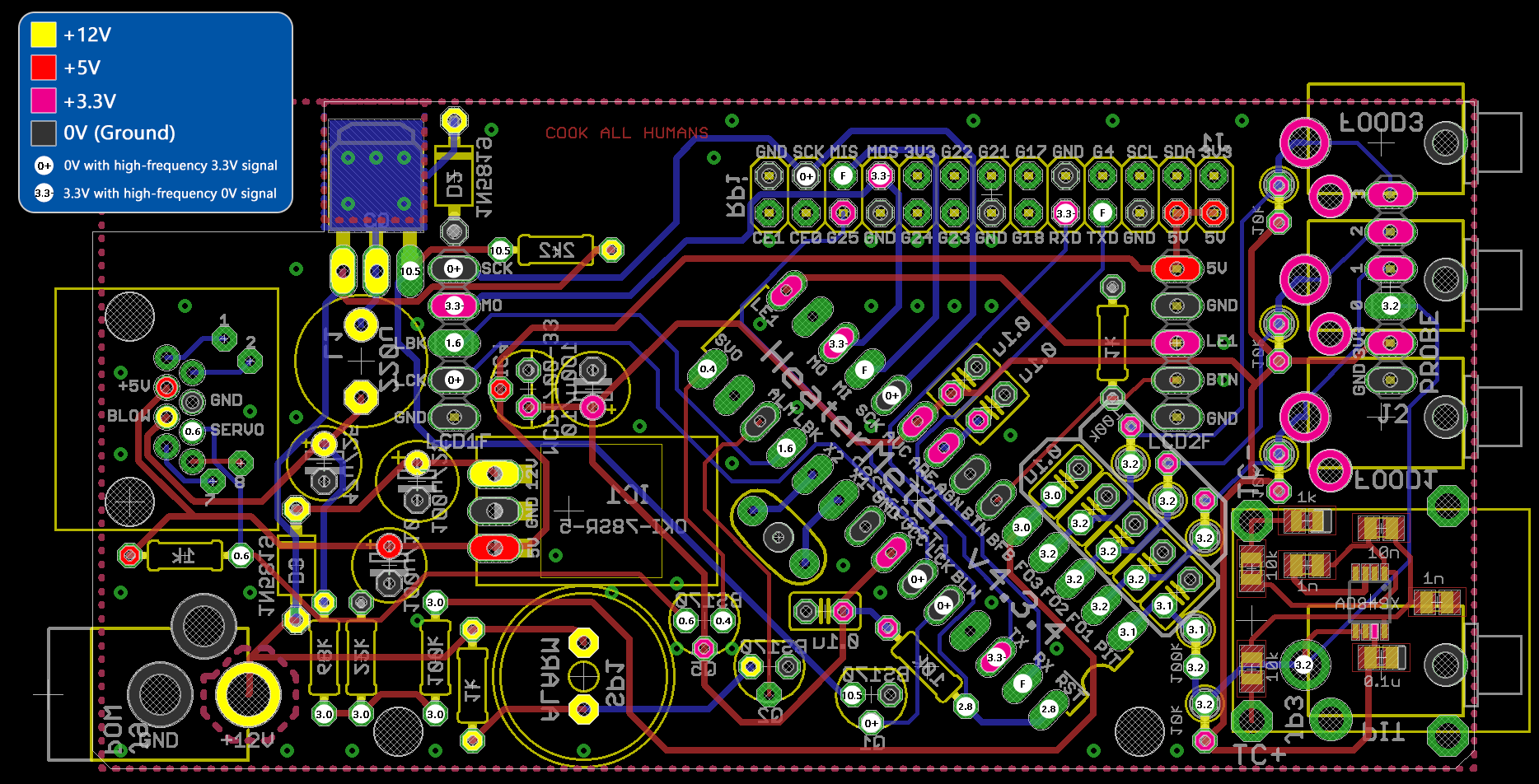
and just look at the board image:


See the red lines that connect those pieces? Everything that has a red line connecting it should read as connected on the multimeter, and if a red line doesn't connect two things and they show as connected you've found a problem. Pins 2 and 3 of the thermocouple amp are in fact connected to ground even though it isn't shown on the image (they're connected to the top copper layer with little tiny pluses on their pad in real life).
Pin 1 - to right side of the 1n capacitor, left side of 10n, and bottom of TC- 10k
Pin 2 and 3 - GND
Pin 4 - Nothing
Pin 5 (bottom left in installed position) and Pin 6 - Big circle (3.2). This is the output
Pin 7 - 3.3V and left side of 0.1u capacitor
Pin 8 - Left side of 1n capacitor, right side of 10n, and top of TC+ 10k
The opposite sides of both 1n capacitors and the right side of 1k are GND.

The first two you can't use since they are digital and we need an analog output. Practically this will limit you to only using the AD8495 chip, as I don't think there are any others which have breakout boards available on eBay or Adafruit. Adafrult's AD8495 is here, and the bottom item you linked from eBay is also appropriate. Both of these have their output shifted up so you'll see that precision reduction and will need to enter an offset into the webui. To use them you just wire VCC to the 3V3 pin of J2, and GND to GND, and output to 0 (Probe 0) on J2. You'll need to disable your amplifier though because they both can't be active at the same time. You can do this by cutting the red trace going to the "3.2" circle, or removing your amplifier.
 
Okay, I've found the issue, I'm just not sure what causes it.

I get no voltage on the J2 probe 0 point. following this back I have continuity beween the J2 probe 0 and the bottom leg of the 100K resistor and continuity between the other leg of the resistor and the PIT pin (pin 1?) on the big chip but I don't get any voltage on any of that when the unit is powered on.


The more I fiddle with it the worse it looks, I've convinced myself I've got the wrong resistors in the wrong holes pulled them out and re soldered them a couple of times now.

 
Last edited:
I haven't followed every post of this thread closely, but if you are saying you have continuity between J2 Pin3 (Pit Probe) and the 100k resistor, and continuity between the other leg of the 100k resistor and pin28 (the corner pin) of the ATMega, then you are saying you have something wrong with your TC amp (or HM config settings perhaps).
 
Yeah looks like you've got the right resistors in the right place, although it looks like the 10k was in there too for a bit ;) The continuity sounds right as well so it sounds like the amp isn't putting out any output at all.

Check the big circle by TC+ (which is also the output of the amplifier) see if you have anything there, and if not check pins 5 and 6 on the amplifier (tied together as the output). Nothing there? Check voltage into the amp on pin 7, should be 3.3V. If it has voltage and has no output, then I'm going to have to start suspecting the amp might be dead. Usually it outputs close to 3.3V when nothing is plugged in, or if there is a fault in the ground from TC-, the output voltage will just sort of float all over until something is plugged in. If there's nothing coming out, then either VCC (pin 7) or GND (pin 3) aren't connected to the PCB, or the output (pin 6) is not connected to the PCB. If all of those show good connection, the amp is likely toast.
 
Today I get -0.1 on the Circle by TC+ and on pin 6 but 3.25v on pin 5.

I give up... I'm going to order a couple of Thermistors and just use them for now and one of those cheap AD8495 amps off ebay and see if I can get that working when it turns up in 4-6 weeks.

Thanks for all your help!
 
Wow that's interesting. Pin 5 and 6 should be shorted together so they should have the same voltage. The voltage at pin 5 sounds right for nothing plugged. As a final test before you give up, try plugging in a thermocouple and seeing if the voltage on pin 5 (or 6) drops to ~125-150mV if it does, then hot dog, all you need to do is bridge from that pin to the circle and it should work. Pins 5 and 6 should also show continuity to the circle with <1 ohm resistance if you want to check those with the power off, but if only one shows as connected, then you can "just" bridge 5 to 6 to the circle with a teensy strand of wire.

I put just in quotes there because it seems simple enough but when you get in there with the soldering iron and the tip is like 3 pins wide, it's as easy as "just" Brexiting. Although this is probably doable in an evening.
 
Just wanted to say thanks for all the help, I had my first cook with the heater meter this weekend (just 2 thermistors one for the pit and one for the pork butt). no air control yet, other than manually stuffing balls of foil in the intake holes (it's a DIY ugly drum smoker) but the graphing of the temperature made it much easier to see what was going on.
 
Last edited:


Back
Top