New build issue


JJenkins

New member
I just finished building a new HM 4.3....and of course it doesn't work. I get a green and yellow LED constantly lit, and no red. The Raspberry Pi Zero W is flashing. I tried accessing the zero not connected to the HM boards and was able to access the web interface. I don't see any obvious solder problems...

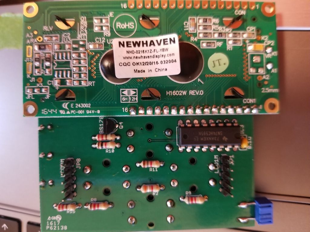
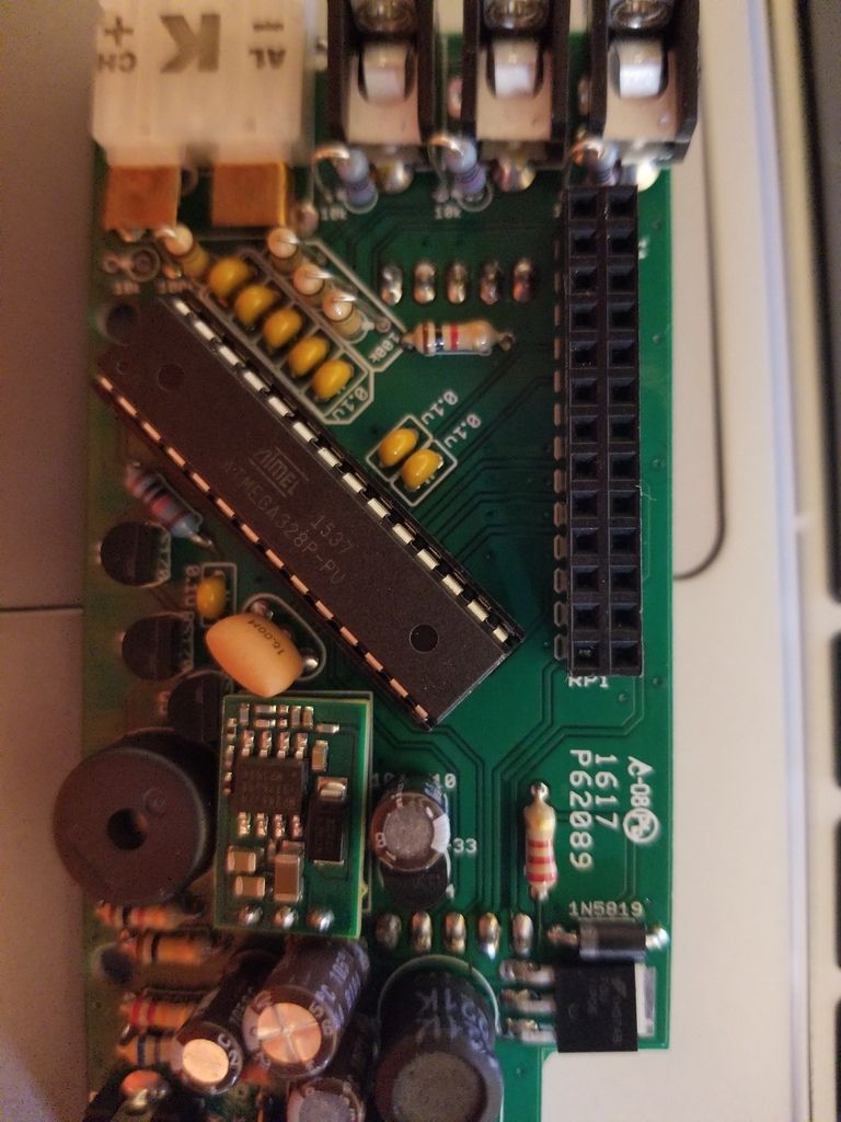
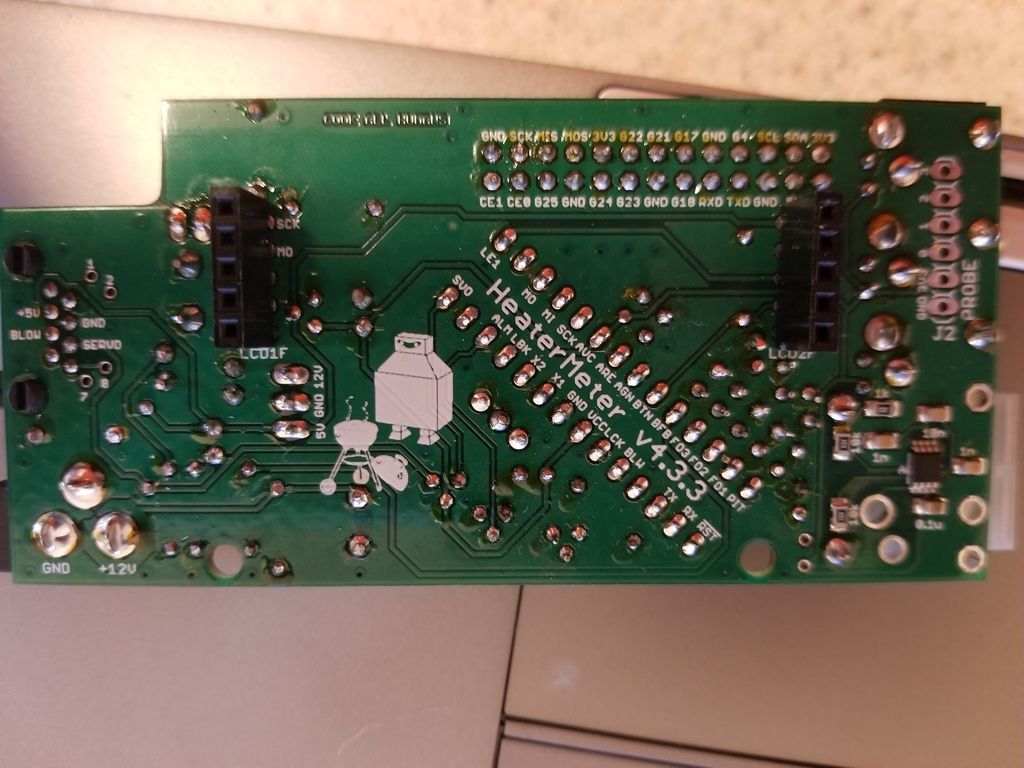
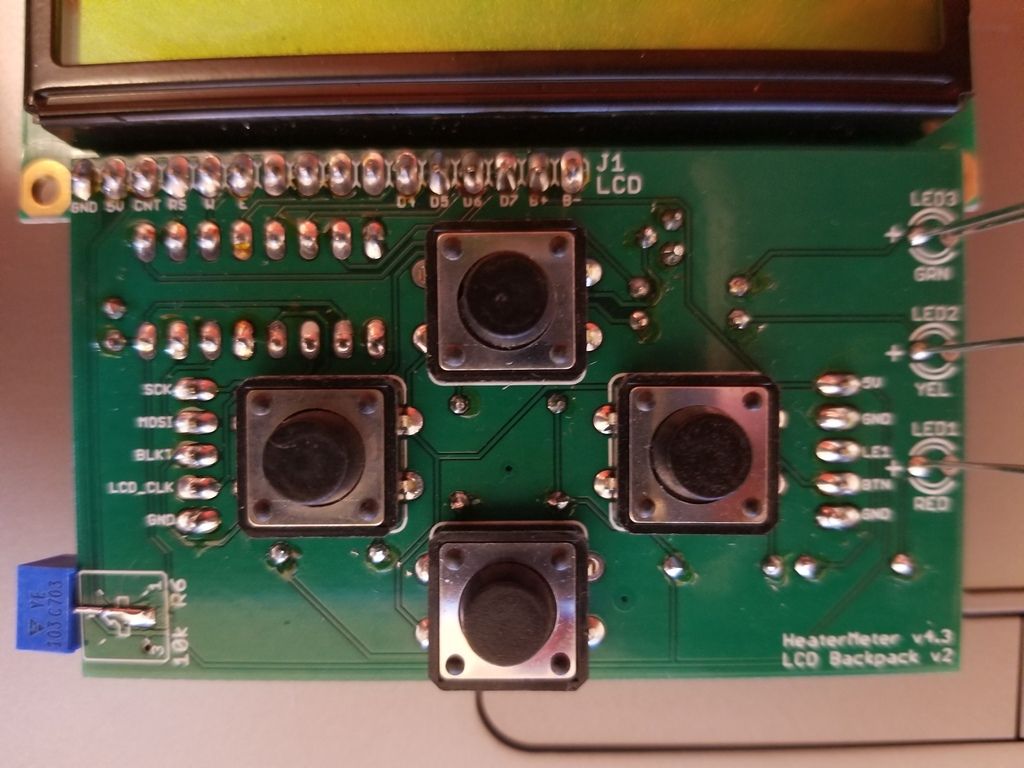
I have attached pictures of my boards here...

Jon


Last edited:
I can't see your pics, but have a few question/suggestions...
What software build are you using? I'm not sure if the zero-w is supported in the release version, you may need to use the snapshot release found here... http://heatermeter.com/dl
Make sure to select the proper target board before you download. I would try the client mode DL at first with your wifi settings, if that doesn't work then try the Access Point download and use a wifi device (like a smartphone, tablet etc) to scan for available hot spots and look for HEATERMETER. If you see it connect with your phone and you should be able to hit the HM interface. From there you can scan for your home wifi and connect via the HM interface.
 
Are you sure you're mating the RasPi up with the HM board in the correct orientation?

Sorry for the preschool photoshop job. This is what it should look like.

6zEdVHD.jpg
 
Last edited:
I downloaded using the download tool and chose:

HeaterMeter Firmware
Version Latest Development Snapshot
Target board Raspberry Pi A/B/Zero/Zero W/A+

I can access the webpage when booted, but the green and amber lights stay lit, no display.

I assumed it wasn't booting (my bad), so I tried plugging in probes, and am not getting anything but I found:

"HeaterMeter serial communication can not be established. Configuration requires bidirectional serial operation. Possible causes of failure:
No HeaterMeter board attached
No HeaterMeter (AVR) firmware installed. See AVR Firmware
Incorrect baud rate in /etc/config/linkmeter
Hardware malfunction"

Tried flashing AVR using:
Flash v4.x snapshots/trunk/heatermeter.hex Sat Sep 16 2017 10:12:45 GMT-0400 (Eastern Daylight Time) 0a547735921362476f91976c16ededff

Received error:
Downloading 'https://heatermeter.com/devel/snapshots/trunk/heatermeter.hex'
Connecting to 104.223.92.144:443
Writing to '/tmp/hm.hex'

/tmp/hm.hex 100% |*******************************| 64000 0:00:00 ETA
Download completed (64000 bytes)
Stopping LinkMeter OK

LinkMeter platform is BCM2708
Loading SPI modules...
AVR fuses ERROR

Starting LinkMeter OK


So.....now I'm lost...I see the error but not sure what it means. I'll do some googling...

Jon
 
OK, so your pi is booting the HM software, but its not communicating with the HM, so, hardware/build issue and your AVR (ATMega chip on the HM) likely hasn't been flashed with the HM firmware...
I haven't built a 4.3 yet so I am unfamiliar with the parts layout, but I would suggest you check the polarity on all of the electrolytic capacitors, diodes, make sure you've got the 3.3v regulator in the right place (it looks exactly like the other small transistors on the board, only the printing is different). Then check your voltages, 12V in, after the 5v regulator (OKI daughter board) and the 3.3v regulator. There's only a few traces that transmit data to/from the rpi, check the schematic for pin numbers and then inspect soldering on both ends. New build troubleshooting 101....
 
Maybe I'm doing something wrong...however:

I checked the voltage between AVC and GND and got 2.72. Between VCC/GND and RST/GND I get 3.25. I tried hitting each of the contacts and reseating the PIC and still get the same results.

Jon
 
I've checked the schematic, and several of the points that according to HeaterMeter433BaseV.png should be 3.3V, are registering at the 2.72 to 2.74 such as G25. One thing I'm not sure of is the 10K resistor in the AVC circuit (from what I can tell from the diagram), has a 3.3V reading on one side and a 2.74 on the other.

Jon
 
Those ~2.70V voltages are way beyond tolerance for 3.3V, although the 3.26V seems fine. You can try pulling the microcontroller out and measuring the voltage with just the HeaterMeter base board by itself (no LCD/Button or Pi). You should still see 3.3V at RST, VCC, and AVC. The pins PIT, FO1, FO2, FO3 should also read within ~150mV of 3.3V. If it all checks out, then add the Pi back and make sure you get the same readings. If that's fine, remove the Pi and try it with the microcontroller plugged back in.
 
With just the board connected (no rpi and no atmega chip), RST/VCC/AVC all show 3.25-3.26. PIT shows 3.18, FO1/2/3 show 3.22.
I checked for continuity between any two adjacent pins on the atmega or the rpi header and showed nothing except for the two adjacent 5v pins on the rpi header.

I checked for continuity between the MO - MOSI, MI - MISO, SCK - SCK, and RST - G25 and got good connectivity.

When the rpi zero plugged in RST drops to 2.7, all the other voltages stay the same.

Where do I look next?

Jon
 
Well that's just bizarre. I just tested my HeaterMeter here and it does the same thing-- connecting the Base board to the Pi, the RST line drops to 2.7V. That indicates that there is a 60uA current draw on that line, when I thought the pin on the Pi is supposed to be high impedance. Apparently looking in the BCM2835 ARM datasheet GPIO 25 is initialized in INPUT mode, except with a pulldown enabled. I guess I just learned something!

Not that that solves your problem at all, but it does indicate that the values you're reading are correct. I can't imagine what else could be going wrong, unless the microcontroller was somehow damaged. There could be a first time for that happening. Do you have any other "Arduino" DIP chips (Atmega328-PU) you could try a swap with to test? If not I could send you out a new chip. It's the only thing I can think of trying although I am skeptical of it being that, as the chips have been proven to be fairly resilient to abuse.
 
Went and pulled my old Heatermeter 4.X board out and took the ATMEGA chip from that, and now it boots!!! I logged into the webpage to test, and plugged in a thermister and thermocouple and both appear to work. Of course, now I find the display isn't working. I've adjusted the contrast and can get the black boxes to show up. I hit the JP1 and JP8 connectors and didn't make a difference. I'll find the diagram of the board and start checking connections. Any specific ones I should check first?
 
Ah ha! Well this is an interesting development. The LCD is driven by.... the SPI bus, the same thing used to program the chip! It sounds like there's a problem in the connection in the DIP socket or something that's preventing the signal you've traced out as working from actually getting to the chip and vice versa. Either that or two pins are shorted, which sounds like you've checked already.

The LCD driver circuit is MO -> MO on LCD header, SCK -> SCK on LCD header, LCK -> LCK on LCD header. Check not only the connections from the microcontroller to the pins on the left 1x5 LCD header (LCD1F), but also check from the solder side of the pin on the 1x5 header to the actual pin of the ATmega to make sure you've got continuity all the way through the DIP socket. It's gotta be something on either the MO or SCK pins.
 
I checked continuity from the ATMega chip leg through to the LCD1F pins for MOSI, SCK, and LCD_CLK and it all looks good. I see the backlight come on when I power it, and adjustment will get both lines of black boxes (first the top then the bottom).

Checking for pins that are shorted together on the LCD board, the only thing I find is on IC3, the third and fourth pins from the bottom right which show 0+ in the diagram (just above the left button) have continuity.

JOn
 
Ah! Those two pins should not have continuity. The pins starting on the bottom right of IC3 are:

Not Connected
+5V
SCK
LCD_CLK / LCK
Not Connected

So pop the LCD board off and see if those two pins have continuity together still, which would indicate the issue is on the LCD/Button board side. If they're not connected now, the issue is on the Base board side. Once you figure out what side it is on, you just need to figure out where they are touching each other.

My lack of skills killed the board, i peeled up one of the traces trying to (and breaking the chip in) the process of removing the chip.

Is it possible to just order a replacement PCB?

Jon
 
Oh no! I should have been more clear. I didn't mean to take the LCD off the LCD/Button board, I mean to pop the LCD/Button board off the Base board. This was a fully non-destructive test. Thinking about it more, did you have the LCD/Button board attached to the Base when you tried to flash the AVR Firmware? If it still won't flash without the LCD/Button board attached, then that still means the problem is in the Base board. Check there to see if SCK and LCK have continuity (they should not).

As Ralph said you can just run jumper wires over a pulled-up trace and connect it. If you need to order half a kit or something, just email me heatermeter@capnbry.net and let me know what you need and we can try to work it out.


Back
Top