Did something wrong..


TB Gallant

TVWBB Member
Ok, so have it all assembled and was firing it up to do some testing. Few notes about my build:

- no LCD or button (back ordered, didn't want to wait)
- wired in 'remote' power and fan connectors

So was able to get openwrt loaded on the Pi pretty easily, and when using the USB power direct to the Pi it loads what I think is fine (HDMI hooked up, goes to command prompt).

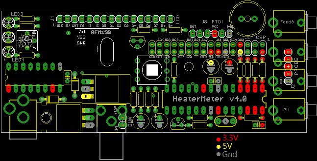
When I plug the HM on there, and use the DC power to it for power (wall wart 12V with 1.5 amp capability).. the red light on the Pi comes on, none of the HM LEDs comes on, and nothing happens. No output through the HDMI (not sure if I'm suppossed to see anything there or not). Also, fairly quickly (5-10 seconds), the "D17" on the Pi get's fairly hot. I think there is also a component on the HM getting hottish as well (maybe a diode or C2.. that area).

So I unplug just to make sure I don't ruin anything (if I didn't already). The Pi boots up to the command prompt (using USB power, HM not plugged in) just fine.
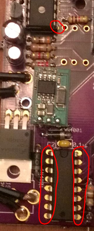
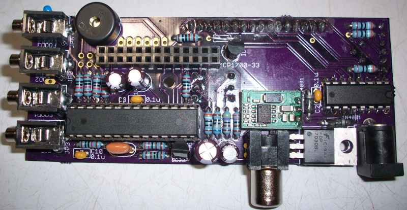
Some pictures:

2013-05-24%2022.25.14%20%28Custom%29.jpg

2013-05-24%2022.25.51%20%28Custom%29.jpg


Likely not giving you much to work with.. but.. help! :)


Thanks

Tim
 
If the bottom LED comes on when you plug 12V in, you were right to stop because something is wrong and you could damage your Pi. Disconnect the HeaterMeter from the Pi and install the IC4 if you haven't already. Then try firing it up on 12V and check things with a multimeter to see where it is going wrong. There's a board image on the forums here somewhere where I labeled what voltages are supposed to be at a dozen locations, which really should be in the wiki so if you find it, please link it so I can do that.
 
Thanks guys.

I wasn't pluging them both in at the same time. With the HM connected I only tried to power with 12V. Bryan, when you say "bottom LED comes on", do you mean the red one on the Pi itself? Does this mean that when working correctly the LEDs on the Pi should never come on when being powered through the 12V / HM?

I don't have the IC4.. :( I didn't order it as I didn't think I needed it. Can I do any tests without it (I guess I"ll need to order it..).

Thanks

Tim
 
I would start out making sure you have all the diodes and electrolytic capacitors installed in the proper direction, then make sure you didn't put an improper resistor value anywhere. Also, make sure you have soldered the chips well enough to get solder to flow to the other side (component side) of the board. My HM didn't power up first time around cause solder didn't flow to the component side to complete the circuit.
If you are finding parts out of stock at Mouser or Digikey just copy the manufacture part number and search the other supplier. There were a couple things on the Mouser list they were out of but Digikey had them, and a couple things DigiKey was out of that Mouser had. Also, there is an alternate 4 line display you can get on ebay for cheap, http://cgi.ebay.com/ws/eBayISAPI.dll?ViewItem&item=161032677017#ht_712wt_1003 , I ordered two and the guy got them to me really fast.
Good luck!
 
I did go over the assembly and all looks good, will try again I guess. I'm still hoping to get an idea of what should happen with the HM LEDs and the Pi LEDs on first (and following) boots. Might help me figure out what is wrong?

I did find the picture with the voltages.

hmpi-power.png


I plan on trying to check these quickly by supplying 12V to the HM and leaving the Pi unconnected.. see what I can get. I may also connect the Pi and see what changes (for short periods of time as I don't want to burn anything up). I'll report back and see if I can get to the bottom of this.

Appreciate the help guys.

Tim
 
I saved the image of your HM board to my hard drive and then zoomed in to have a closer look. I see in the picture that the traces under the IC's are still GOLD, meaning solder hasn't flowed onto them. My initial power-up failed because solder didn't flow to the component side on the IC's, when the rPi fired up the first time it tried to program the ATMega but failed because solder hadn't completed the circuit from top side to bottom. There are traces on the top and bottom of the board, if solder doesn't flow to the top (component) side of the board the circuits are not complete.
If I were you I would pull the ATMega out of the socket, then re-solder the socket and the other IC making sure that solder flows onto the gold traces on the component side, then put the ATMega back in and try again. It will likely fail (like mine did) due to a failed flash at first boot, so flash it again and I bet it comes to life...
I circled in red the areas where I can clearly see a lack of solder on the component side of your board, re-solder any areas that look like this....
Solder.jpg

I would pay close attention to the soldering on IC3 (above), all the traces pretty much look gold...
 
Last edited:
On the LED's
At power up my HeaterMeter board does a VERY QUICK flash of RED, then YELLOW, then two flashes of GREEN, then they all go off. It happens very fast, sometimes I can't see the red flash.

On the rPi the LED's are labeled pretty well:

the red one next to PWR is the power LED, it comes on and stays on when the rPi is powered on

the one above that says ACT, guessing its "activity" cause it flashes like a hard drive LED would

The three closest to the edge of the board say FDX, LNK and 100, I assume this is for the wired LAN, LNK lights when linked, 100 lights when at 100 speed, the FDX has me puzzled at the moment, but doesn't light.

When I plug the HM to the rPi and power up, the HM LED's do as described above, and the rPi power LED glows red, the ACT LED flashes occasionally while loading, the other LED's remain off (although will light if you plug in a LAN cable and link to a network/pc)

That should pretty much cover your LED status for you...

HOWEVER, I will note that on my first power up, when my solder on the IC's was bad (like yours appears to be), my LED's were doing all sorts of strange things, including coming on and staying on at times. After I re-soldered and re-flashed my ATMega everything worked like magic! I documented the experience pretty well in this thread, including links to the info that helped straighten me out, perhaps you should read it... http://tvwbb.com/showthread.php?40900-Initial-Power-Up-some-issues-eventual-SUCCESS!
 
Thank you VERY much, this is great stuff. I'll be sure to take your excellent advice and give it another go. I was fairly quick with the soldering of the socket/IC because I didn't want to overheat anything (and it seemed really easy to get solder to fill the bottom side, but not good enough for the top side as you pointed out).

Thanks for the LED info, it should help a lot diagnosing in the future if things aren't quite right.

Cheers!

Tim
 
Yeah checking all the points on that image above with a multimeter would be a good place to start. It looks like your yellow LED is in backward too (unless yellow LEDs have backward looking anode/cathodes), but I don't think that would cause any problem other than preventing the LED from lighting.
 
I just pulled my HM apart and did some comparison to your picture. Your diodes and caps all seem to be facing the right direction, HOWEVER, IC3 (the second largest IC chip) appears to be installed BACKWARD. If you look at the ends there is a horseshoe shaped indentation on one end of the chip, and there is a similar horseshoe shape in the printing below that shows how the chip should be installed. Your chip does NOT match the printing below..... That would be a big issue!

Beyond that, a quick look over your resistors and they don't seem to have the same color codes as my board, in other words, it looks like you have the wrong value resistors in some places. I am wondering if you ordered these parts with the Mouser project parts list provided on the Heater Meter project page? You need to make sure you have the right resistors in the right places! Beyond this Bryan pointed out one of your LED's appear to be installed backwards....

Bottom line, it seems you didn't do a very good job of putting the right parts in the right places, and when you did get the right parts you sometimes got them in backwards.....

If you ever want your HM to work you need to take a step back and correct all your mistakes. First off you need to remove that IC3 and install it in the proper orientation, with the horseshoe shapes aligned on the IC and the print below. Then go through and check what value resistors you put where, for example, the 4 resistors in a row right below the probe inputs, on my HM they are all the same value/color code, on yours two appear to be different? There are quite a few other resistors that do not seem to have the same color codes as what is on my board, not sure if it has to do with how colors show in your picture, but there are quite a few that seem to be wrong.....

I don't intend to discourage you, but your HM board is AFU, it's no wonder it is not working! We are here to help you, but you need to take stock of what you have done, right and wrong, and correct your mistakes. Did you happen to order any extra resistors when you ordered parts? You usually can't get an accurate reading on a resistor with a multimeter while it is in circuit, if you have spares that are in a bag with the value marked on it that can help you identify what value resistors you put where, or you can measure the value of them while out of circuit with a meter. I know the value for the resistor are all printed below the resistor, so its hard to tell what value should go where after it is assembled. I ordered a second HM board that just shipped recently, if/when it arrives I will take a picture of it and post it here so you can read the values printed on the unassembled board. (Unless Bryan or someone else has a picture like that to post?) If I were you I would NOT apply power to your HM board or connect it to your rPi again until you have gone over your HM board with a fine tooth comb and are SURE all the parts are in the right places and in the proper orientation.....

PS Here is a web page that explains the resistor color code:
http://www.allspectrum.com/store/resistor-color-code-chart-all-spectrum-electronics.php
 
Last edited:
Hi Ralph,

I agree, that IC3 looks to be flipped, shoot! I did understand the directions and tried to install it the right way. Looks like I may have messed it up in the process of 'bending the pins' in a bit to get it to slip into the board.

As far as the resistors, my order came with two incorrect resistors so I had to sort through my stash and find some replacements. I did measure them (before inserting into the circuit) to ensure they were the right value, but there is a chance (obviously) that I missed one. The 4 in a row are for the probes, I am using ET-732 probes so I used 22k resistors in place of the 10k for two of the probe locations. I'll be sure to compare the color codes on all my resistors to ensure they are right.. which might be tricky as I don't have a picture of an unpopulated board.

Thanks

Tim
 
I was hoping my spare HM board would come in the mail today, but the mail was just delivered and no board...
I snapped a clear picture of my assembled (working) HM board that you can use for reference on the color codes etc....
HM.jpg
 
I just noticed you are in Canada, and likely had to source your parts in country rather than from Mouser and Digikey... If you measured and checked your resistor values when building you should be OK, there aren't too many to worry about, you can compare to my board above to be sure.
At this point, if I were you I would remove that backward IC and get in installed in the proper orientation, touch up the soldering on the ATMega socket and also make sure IC3 gets soldered in well (solder flowing to the component side of the board), and check the orientation of your LED's while you are at it (as noted by Bryan, the yellow may be backward). Then I would power the HM board (alone) and see what happens (mainly with the LED's I guess since you don't have a display). I'm not sure what to expect from the LED's honestly, since your ATMega chip has likely not been flashed by the rPi yet, so it is probably blank or mis-programmed at this point. So I am doubting your HM LED's will do the same thing as mine which has a properly programmed and functioning processor.
If you feel you have corrected all mistakes and see the HM on its own behaving better, then plug in the rPi and power up the unit and hope for the best. You will likely have to force the rPi to flash the ATMega before your HM will work. To do this, from the rPi console enter this command:
avrupdate /lib/firmware/hm.hex
It should erase then program the ATMega chip on the HM and THEN you should have a functioning HeaterMeter.... hopefully....
 
I just pulled my HM apart and did some comparison to your picture. Your diodes and caps all seem to be facing the right direction, HOWEVER, IC3 (the second largest IC chip) appears to be installed BACKWARD. If you look at the ends there is a horseshoe shaped indentation on one end of the chip, and there is a similar horseshoe shape in the printing below that shows how the chip should be installed. Your chip does NOT match the printing below..... That would be a big issue!

Beyond that, a quick look over your resistors and they don't seem to have the same color codes as my board, in other words, it looks like you have the wrong value resistors in some places. I am wondering if you ordered these parts with the Mouser project parts list provided on the Heater Meter project page? You need to make sure you have the right resistors in the right places! Beyond this Bryan pointed out one of your LED's appear to be installed backwards....

Bottom line, it seems you didn't do a very good job of putting the right parts in the right places, and when you did get the right parts you sometimes got them in backwards.....

If you ever want your HM to work you need to take a step back and correct all your mistakes. First off you need to remove that IC3 and install it in the proper orientation, with the horseshoe shapes aligned on the IC and the print below. Then go through and check what value resistors you put where, for example, the 4 resistors in a row right below the probe inputs, on my HM they are all the same value/color code, on yours two appear to be different? There are quite a few other resistors that do not seem to have the same color codes as what is on my board, not sure if it has to do with how colors show in your picture, but there are quite a few that seem to be wrong.....

I don't intend to discourage you, but your HM board is AFU, it's no wonder it is not working! We are here to help you, but you need to take stock of what you have done, right and wrong, and correct your mistakes. Did you happen to order any extra resistors when you ordered parts? You usually can't get an accurate reading on a resistor with a multimeter while it is in circuit, if you have spares that are in a bag with the value marked on it that can help you identify what value resistors you put where, or you can measure the value of them while out of circuit with a meter. I know the value for the resistor are all printed below the resistor, so its hard to tell what value should go where after it is assembled. I ordered a second HM board that just shipped recently, if/when it arrives I will take a picture of it and post it here so you can read the values printed on the unassembled board. (Unless Bryan or someone else has a picture like that to post?) If I were you I would NOT apply power to your HM board or connect it to your rPi again until you have gone over your HM board with a fine tooth comb and are SURE all the parts are in the right places and in the proper orientation.....

PS Here is a web page that explains the resistor color code:
http://www.allspectrum.com/store/resistor-color-code-chart-all-spectrum-electronics.php

wow nice catch ralph
that was impressive.... but..... if you are commenting on his blue resistors... that is what mouser sent me and i ordered right off the parts list... BTW bryan if you can i recommend you add a IC socket like you have for the atmega chip if the clearance wont be to high.... only cause that will make life alot easier in soldering and correcting mistakes.
I cant imagine trying to desolder that thing.... i honestly would just order a new one... but it can be done... if you do decide to fix the board: do your self a favor and get a socket like the atmega chip has. also order urself a new ic3 chip.... it will make life easier cause then you can clip all the connections and pull it out piece by piece. well good luck!!!!

I think you are commenting on the picture of MY board, which has the blue resistors (from Mouser). His board is the one with the chip installed backwards! LOL
As for desoldering that chip, fairly easily done if you are experienced with electronics. If you have a de-soldering iron that would be easiest, if not then a regular soldering iron and a solder sucker, or just go at it with some solder wick if you are lacking tools. You should be able to get it done without killing the chip, just take your time, do little parts at a time so the chip doesn't heat up. Eventually it will be loose enough to pry up with a small screwdriver, but don't force it if it doesn't want to move.....
 
A socket for the IC3 chip is a good idea. The question then is will there be enough room with a socket involved. Am still waiting for the rest of my part so I still have time to get a socket locally. Any thoughts?
 
It's been brought up before but I find the concept of the socket for an fixed-function IC to be silly. If you put in the voltage regulator backwards you'd fry something too, should it have a socket? Sockets for every component! Considering they cost about the same amount, maybe I should just put 2 of them on the parts list :)

Also I think it might be too wide to fit with the headphone jack in the way considering the socket is slightly wider than the chip. It might be cheaper to get the part from eBay shipped from USA with free shipping. 10x for $3 shipped


Back
Top