HeaterMeter + LinkSys WiFi Router = LinkMeter


Software source code is available on my github
GitHub master branch

I suppose it is past time for me to chime in after Ed has already gotten the thread rolling with all the great pictures descriptions. Makes me feel like I need to go back in time and take more photos of my build process on HeaterMeter.

On the software side of things, let's talk about the differences between HeaterMeter and LinkMeter. The obvious advantages of using a DD-WRT router as a WiShield replacement are two-fold:

1) Power! I'm talking about raw CPU power, memory, storage, and bandwidth. The CPU of even the lowest end routers are 10x more powerful than an Arduino. The Arduino only has 32K to store code in, the router has 128x that and it is easily extended by adding either an SD card or USB storage. There is also a full TCP/IP stack which means you're not limited to sending 250byte payload packets 5/second to only one host at a time.

2) Cost (if your time is free). The beauty of the WiShield is that you plugged it in, uploaded your web pages and you were done. The downside of that is you paid $70 shipped for pretty limited functionality. WRT54GLs can be had for $10-50 and are in ready supply. However, you'll need a little more work to modify it to suit your needs as Ed has demonstrated.

Instead of the Arduino controlling the WiShield and the Grill, the Router controls the Arduino which has the sole purpose of controlling the grill, buttons and display.

What enhancements can we now provide?
Now that we can remove the TCP/IP and webserver code from HeaterMeter, we now have lots of code space available again, available to enhance the operation of the PID controller. The extra storage space means in addition to providing the instantaneous readings of temperatures and fan speeds, we can now maintain logs. I'd like to have the ability to archive these to SD/USB so you can go back and look at them for reference.

The best way to do that is via graphs. I've already got some beautiful history graphs being generated and stored directly on the router. No external Linux box / gnuplot / curl needed.

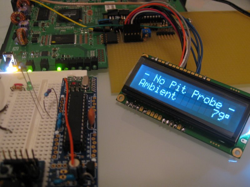
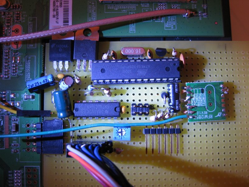
Wireless probes. Ed is on the forefront of this one. Using RFM12B wireless modules (~$7 each), allow for probes to be paired wirelessly. Uses include food probes attached to a rotisserie, easier pit probe access, or an ambient sensor that isn't mounted inside a box of electronics.

Wireless display. I haven't thought too much about this but I've considered making unit with the LCD wireless. This could give you a small form factor for easily checking temperature remotely without using a web browser, or physically getting up. This is pretty low on my priority list.

The auditory alarm code is now back on the table. High/low alarm points to sound an alarm or beeper. Used for when your food is done or your fire is going out.

PID enhancements like "ramp down" mode. If you set your probe target temperature to a value, the pit temperature can be ramped down to meet that target temperature.

Better web configuration pages and finer control over the algorithms and data produced.

Unknown probe Steinhart-Hart calibration. Just plug it in with a known probe in a pot of cold water on the stove and let us do the math for you. Ideally LinkMeter would not have the Steinhart constants and biasing resistor values stored in code space too. They should be able to be changed on the fly.

Percentage based lid detect. Instead of a fixed number of degrees vary it based on setpoint.

Proportional PID bias. Adjust the "baseline" amount the fan has to run based on setpoint. Something like 5% per 100F over 100F or something?

Probe blending. The ability to take multiple probes and make one virtual probe out of them. This could be used if you want a probe at grill level and one in the dome and want their average to be the setpoint. I don't know if that will work but it is something I'd like to try.

Multiple grill outputs? I'm not sure about that one.
 
Well score, the auction I won on ebay last weekend for a WRT54G v2 came today but its a WRT54GS v2. Yay for twice the memory! I will be catching up to this project shortly.
 
You guys are my heroes. I am only a moderately experienced electornic kitbuilder with no real understnading of how to design the things i am soldering, and have just been able to make leds flash on and off in arduino but not do code beyond that, so I will study this carefully and then hopefully dive in with both feet. This looks like a lot more fun than buying a bbqguru (if I can get it to work). One question -- the arduino will drive a 25 cfm 12 volt blower just like the smaller blowers, with no code revision, right? I have a Rocky Mountain for which I will get a smaller blower, but also a larger offset barrel smoker than needs a bigger blower (I think). Thanks.
 
Originally posted by rob blum:
One question -- the arduino will drive a 25 cfm 12 volt blower just like the smaller blowers, with no code revision, right? I have a Rocky Mountain for which I will get a smaller blower, but also a larger offset barrel smoker than needs a bigger blower (I think)
You might need to adjust the parameters of the control loop to fit the characteristics of the fan better, but this will be able to be done from the web site.

You'll also need a 12V power supply that can power it. Router power bricks are usually only good up to 1A total power draw. And although the power MOSFET we use is good up to 4A, it will probably need a heatsink.
 
*** This documentation is preliminary and in flux *** this is still very much a live project with a lot going on. I haven't gotten a LinkMeter router yet, so I'm using one that has USB storage. The paths will be different, but either works. I'll fix this post once I have the proper hardware assuming I don't to something to make it burst into flames or crush a SMT capacitor and render it useless.

Packages
DD-WRT can load extra packages from the OpenWRT software server. We'll need two so ssh or telnet into your router and run the following
ipkg update
ipkg install rrdtool
ipkg install lighttpd

It should download a bunch of other dependency packages, such as libopenssl and libpcre. When you're done you should be able to type
rrdtool

and get some usage information about rrdtool. If not you'll have to figure out why ipkg is being a total jerk about it. The ipkg tutorial might be some help. It wasn't in my case but maybe you're a better reader than I am. Hey, you're reading this right?

LinkMeter Files
You'll need to download the LinkMeter suite. The latest software is available from github
Download: GitHub HeaterMeter Project

Get all the source from the master branch. The part in the arduino directory you'll need to flash to your ATMega, the stuff in the router directory goes on the router.

Copy the entirety of the router source directory to your router into the document root for lighttptd. On my router this is /opt/share/www/. It might be in /jffs/share/www.

Depending on what system you're copying from, some of the file properties might not have been preserved. This is true if you copied them from a Windows system to the router. No worries, we'll just reset them back to being executable. From the lighttpd document root:
chmod +x create_hm_rrd
chmod +x getdata_serial
chmod +x cgi-bin/set
chmod +x cgi-bin/hm_data

Configuration
We need to enable cgi access in lighttpd and also move it to another port. The DD-WRT configuration web server runs on port 80 so for now we'll just run LinkMeter on a different port. You can modify the DD-WRT web server to run on a different port too, but I had little success in making that work. Edit the lighttpd.conf. This is in /opt/etc/lighttpd/lighttpd.conf for me, but try /jffs/etc/lighttpd/lighttpd.conf if you don't have that. Near the top, find the line that says:
server.event-handler = "epoll"
and change "epoll" to "select". Right below that

# "mod_cgi",
remove the # symbol from it. The hash symbol "comments out" the line so removing it activates the cgi module in this case.

Also zip down to server.port and change that to something else like port 81
server.port = 81

After that line add our CGI declarations (a new line)
cgi.assign = ( "/hm_data" => "", "/set" => "" )

Restart lighttpd. You can do this my rebooting the router, or
killall lighttpd
lighttpd -f /opt/etc/lighttpd/lighttpd.conf

Finally, you need to edit the heatermeter.conf file in the lighttpd document root to match your configuration. Specifically you might need to modify SERIAL_DEVICE and probably need to modify RRD. Where your rrdtool is located can be determined by typing
which rrdtool
At a command prompt.

Fire it up
Start the data collector process (the path is the path to the lighttpd document root)
/opt/share/www/getdata_serial &

If all goes as planned within 2 seconds there should now be a /tmp/hm.rrd, a /tmp/json, and a /tmp/data.txt. If you only have the first file, we're not getting any data from the Arduino. You're on your own on that one.

Fire up your web browser and go to http://routeraddress:81/

Start cooking!
 
Ed is the King of building things, and also of this thread, but I'm pretty stoked that I've built the majority of the insides of my LinkMeter. Here we have the HeaterMeter guts stuffed inside of a Linksys WRT54GL and hooked to the serial port. The yellow wire pulls 12V from the power jack to the system
linkmeter-2011042401.JPG


The back side
linkmeter-2011042402.JPG


Yay! Not obvious but the display is running at 50% backlight because new feature
linkmeter-2011042403.JPG


My implementation is slightly different than Ed's. I use the 3.3V directly from the serial header and buffer it with a 330uF capacitor (the big green one laying down on the left). The LCD uses 5V, so I pipe that in through the 12V power jack, through a LM7805 (top left) and use that to power the LCD logic. This newhaven display will take 3.3V logic so the signals from the 3.3V Arduino are fine. The backlight is run from a PWM pin on the Arduino running into a BC337 transistor bumping the voltage and current from 3.3V/0.3mA to 5V/~20mA.

Oh and don't use vertical headers like I did for the LCD header. They're too tall and I'll probably have to bend them to fit things back into the linksys enclosure.

EDIT: I look at the front of that board and it looks so easy then I look at the back and remember it took me 16 hours to build and debug that. This would be so much easier if one could just print PCBs as easily as one could print something from an inkjet printer.
 
Ed / Bryan,

Finally catching up on this new thread. Wow...nice job guys once again! You are doing a great service to the community by providing such detail and organization. Very much appreciated!

- John
 
Originally posted by John Bostwick:
I am still having problems getting lighttpd running. I have followed every thing in this thread to the T and I have look over the net for differnt things to try and all have failed.
If you type `ps`, does it show up in the process list?
<pre class="ip-ubbcode-code-pre">
PID USER VSZ STAT COMMAND
1 root 1284 S /sbin/init noinitrd
2 root 0 SW [keventd]
3 root 0 RWN [ksoftirqd_CPU0]
...
618 root 2648 S httpd -p 80
2802 root 1204 S -sh
2815 root 3728 S /opt/sbin/lighttpd -f /opt/etc/lighttpd/lighttpd.conf
2816 root 1180 R ps
</pre>

If not try `/opt/etc/init.d/S80lighttpd start`. Still nothing? Check /opt/var/log/lighttpd/error.log for an error message.

I'll make a post with my parts list and schematic, which may or may not be confusing because it is different than the schematic Ed posted on page 1.
 
Parts List:
Atmel ATMEGA328P-PU $4.28
28pin DIP socket $0.30
LM7805 5V linear voltage regulator $0.35
IRL510 MOSFET $1.46
16MHz crystal (optionally you can use a ceramic resonator instand and skip the 22pF caps) $0.55
22uF 25V electrolytic capacitor (I used a 50V but 25V would be smaller) $0.02
47uF 25V electrolytic capacitor (anything from 47uF to 100uF is fine) $0.05
100uF 6.3V electrolytic capacitor $0.27
330uF 6.3V electrolytic capacitor ??~$0.50
2x 0.1uF multilayer ceramic capacitor $0.10
2x 22pF ceramic capacitor $0.20
3x 10K ohm resistor 1% 1/4W $0.30
2x 10K ohm resistor 5% 1/4W (you can use 1% tol instead) $0.10
3x 1K ohm resistor 5% 1/4W $0.10
20kOhm single turn potentiometer 1/4" 10% $0.83
1N914 switching diode (or 1N4148) $0.03
2x 1N4001 rectifier diode $0.20
74HC164 CMOS serial in parallel out shift register (must be HC, not LS!) $0.45
BC337 general purpose transistor $0.05
16x2 5V LCD NHD-0216K1Z-NSW-FBW-L $11.90
Total: $22.04

various pin headers:
6x1 right angle female
2x 6x1 right angle male
3x2 vertical male
6x2 right angle male
5x2 rectangular crimp connector housing
2x1 rectangular crimp connector housing
6x1 rectangular crimp connector housing

Note that 1/8W resistors can probably be used everywhere, I just had 1/4W so I used them. Also looking at the cost, I am wondering if there's a different MOSFET we can use because the cost of that is abnormally high compared to all the other parts.
 
Originally posted by John Bostwick:
one question: How would go about setting it up, so I could view from any computer/phone over the internet?
Hey good work! All I do is poke a hole in my firewall to let the connection in. My home machine registers its IP address withing dynamic DNS updates. I use a custom system, because I have my own domain and servers, but there are a number of dynamic dns services supported by DD-WRT or your existing firewall router:
http://www.dd-wrt.com/wiki/ind...edded_inadyn_-_HOWTO
 
Nice thanks again bryan. it took me a little bit to figure out how to get it to directed to the port but all is good now.

Now the fun begins lol. Can't wait to start the soldering, button board is finished just need something for it to connect to.
 
A little update to keep this thread alive while I work.

We're 95% sure we're moving to using OpenWRT as the base software platform. OpenWRT is just light years ahead of DD-WRT as far as customizing the build image. They've also got a great LUA-based web interface which I like because that means I'll have LUA on-board and that adds a lot of flexibility for the scripts needed for the HeaterMeter operation. The two downsides of using OpenWRT are that OpenWRT doesn't support as many routers out of the box, and that the web interface for an _internet router_ is less functional than DD-WRT. That second one is OK though, because we don't need most of the configuration, we just need a wireless client.

Because the Arduino is housed inside a router, this presents a problem updating the code on it. Also, because we only have serial RX/TX, the standard flashing procedure doesn't work. I've spent a lot of time trying different things and today I've got the ability to update the Arduino code from the web interface. Heck, it can even download the update from the web and install it in about 10 seconds!
 
== CONFIG CHANGE ===
If you're following git, revision 4cf12781f529284fc7b206f93c292f9b5c03e9ac at ~19:00UTC today changes how the LidOpenOffset works. It used to be straight degrees F, but now it is a percentage of the setpoint. This allows you to have tighter control at the lower temperatures (where HeaterMeter is more accurate) without going into Lid Detect at higher temperatures (where the acceptable swing is a bit larger).

The config item is the same so your old degreeF is imported as the percent, which is probably too large. The new default is 6%, which is ~14F at the default 225F.
 
Originally posted by Bryan Mayland:
A little update to keep this thread alive while I work.

We're 95% sure we're moving to using OpenWRT as the base software platform. OpenWRT is just light years ahead of DD-WRT as far as customizing the build image. They've also got a great LUA-based web interface which I like because that means I'll have LUA on-board and that adds a lot of flexibility for the scripts needed for the HeaterMeter operation. The two downsides of using OpenWRT are that OpenWRT doesn't support as many routers out of the box, and that the web interface for an _internet router_ is less functional than DD-WRT. That second one is OK though, because we don't need most of the configuration, we just need a wireless client.

Because the Arduino is housed inside a router, this presents a problem updating the code on it. Also, because we only have serial RX/TX, the standard flashing procedure doesn't work. I've spent a lot of time trying different things and today I've got the ability to update the Arduino code from the web interface. Heck, it can even download the update from the web and install it in about 10 seconds!


Bryan, you are amazing. Thank you so much for your efforts.
 
Soldered my RFM12B chip "deadbug" style onto my breadboard. Works well enough for me!

But what's this? Oh I didn't see that you had an ambient temperature sensor in your LinkMeter. I don't, you fool! The ambient sensor is coming from the JeeNode right next to it, WIRELESS!
linkmeter-2011050401.JPG


Here's what my board looks like after adding the reset pin components and the RFM12B chip on the right.
linkmeter-2011050402.JPG


Still a ton of work to do but at least it communicates. The reliability is not so great, I lose about 1 in 20 packets. The thing is that it is almost impossible to tell what goes wrong there. I mean the things are like 2 feet apart here. If there's some sort of RF tuning problem, I'll never find it with this equipment. I'm thinking the remote nodes might just send their temperature 3 times in a row then go back to sleep. Waiting for acks probably takes more power than just transmitting blindly a few times. Maybe? We'll see. Plenty of experimentation left.
 
Originally posted by Ed Pinnell:
I used to think there was nothing as seductive as the smell of Hoppe's No.9...now, I must confess, there might be others. Your picture of the deadbug RFM12B, with its center-spot lighting, or the picture of the over-exposed LED to the left of the LCD display...well...let me say, if you ever get tired of programming for a living, you are well suited to photographic lighting and composition.
Haha Ed, if I had known you were going to like it so much I would have adjusted the exposure and added a lens flare for you. **** **** **** **** ****!

I also didn't have any 10k 1% tolerance resistors for the build so I just used standard 5% ones. Why is this acceptable? Because LinkMeter supports different Rknown values per probe. So what if one is 9423ohms and the next one is 9967 ohms. I may swap them out with 1% versions just because metal film resistors have less temperature variance than carbon resistors. It may not make a difference but the feature is there (mostly because it is a pain to keep editing the source code to support my other device that has 22k ohm Rknowns).

That feature will be pushed to github once I finish the configuration reorganization. The steinhart values are also stored in EEPROM instead of PROGMEM. All of these changes make me wonder: are there two distinct types of configuration? One set of options that is specific to the device you've built, like Rknowns and steinhart coefficients, and a second set of options like alarms, setpoint, max fan speed. I'd hate to "Reset config" and have to type in my steinharts and resistor values again. Maybe that's the only config that shouldn't reset.

Looking at the WRT54GL, it looks like there's already a 5V synchronous buck converter on board too, so the entire 5V power section of my board can probably be eliminated, considering I only really need maybe 25mA of 5V power max.

Lastly, that looks good, John! Hey on my first build I wished that I would have left more space in between the components because it was hard to make, and impossible to troubleshoot or fix.


Back
Top