Bryan Mayland
TVWBB Hall of Fame
Considering the cost of a WRT54GL, I think the cost of a RaspberryPi + WiFi dongle is in the same ballpark as a low cost homebrew controller.Originally posted by Dave S (GeoDave):
I get my Raspberry Pi this week!
Bryan:
- Are you thinking of an Arduino shield that sits on top of the Raspberry Pi communicating through the SPI?
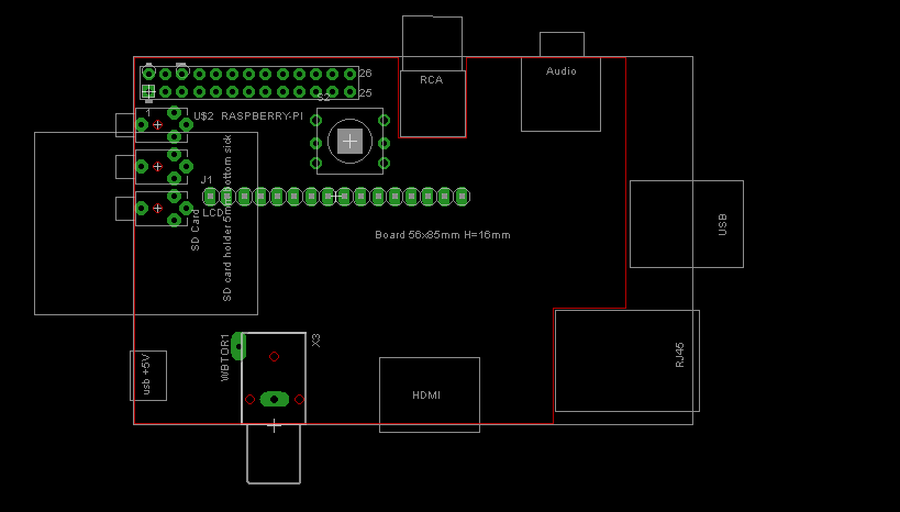
I found a Raspberry Pi library/footprint online. It would be pretty easy to redesign the existing v3.2 board to sit on top of the Raspberry PI.
I guess the alternative is a complete redesign of the entire system.
- If the Arduino is eliminated I think it would be pretty easy to design a shield to connect the sensors/blower/button to the GPIO pins but what about the LCD support?
I am trying to think how a 16x2 LCD could be implemented through the pins available on the Raspberry Pi...

Since you are still volunteering your time to this project, I am assuming you will be writing a standalone program to run on the Raspberry Pi.
- What were thinking in terms of software? Similar interface? Maybe a standalone application in Debian?
- What about a case?
I heard the Pi is pretty delicate. I was thinking it would be cool to create a custom case for the Raspberry Pi plus shield when that designed. Maybe it could be posted to Shapeways and folks could order the design through that site. I read on their site that you can design cases using an opensource software called Blender. The LCD could sit on top of the shield with a button next to it. The button/LCD could be designed to stick out of the top of the custom case. The audio jacks and blowers could go on the side.
Anyway, just trying to get the conversation going. OR is this too costly for the original purpose?
I considered running everything directly from the Pi's ports but the LinkMeter specs I think requires the following:
-- At least 3 ADCs for probe inputs plus 4 digital inputs for buttons, or 4 ADCs.
-- A digital out for the LCD (which is driven over SPI currently)
-- A PWM out for the fan control
-- A PWM out for the alarm
-- Optional digital out for RFM12 and input for interrupt
I think it would be technically possible to do most of the required items, but I'd have to use an SPI or I2C ADC chip. That's going to probably be a 16-pin DIP chip that costs as much as the ATmega so the way I see it, it will probably be easier and more functional to just keep the current ATmega HeaterMeter configuration.
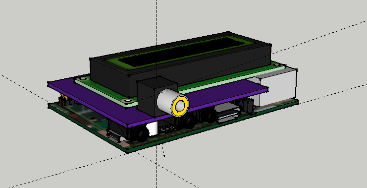
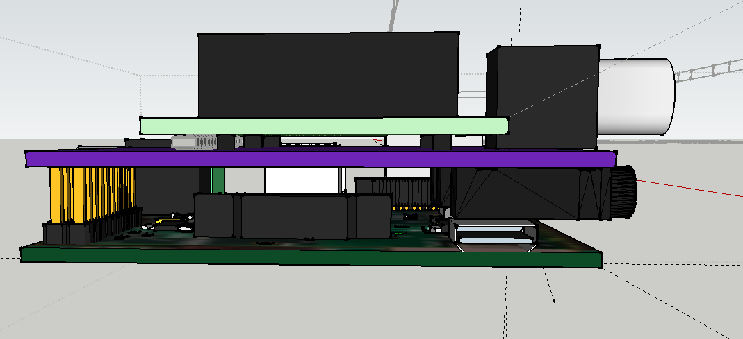
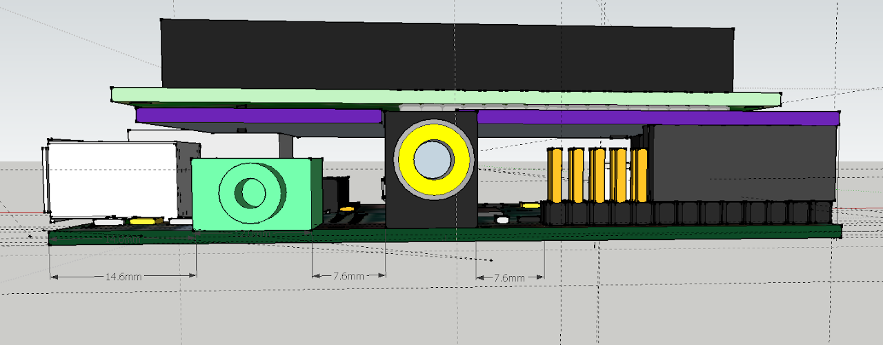
The PCB design I had been messing with would have the LCD and probe jacks mount directly to the board, and possibly even the button too. It was still up in the air how much I could squeeze in, but I've also built prototype cardboard mockups of various exterior dimensions to determine if side-by-side boards would work better with connectors. I should have mine inside of a month or so to be able to play with it. I'd also like to look at getting a smaller software installation for it too. It is amazing that OpenWrt is a somewhat complete ARM Linux server install that fits in 3MB and all the RaspberryPi ARM Linux installs are into the gigabytes.