Thermocouple Board Success (sort of)


Without looking at the datasheet, I'm fairly certain you're quoting from a section about using the sense pin as a comparator for driving the output pin in an on/off digital way. HeaterMeter uses the analog temperature output mode of the device because it can't do PID control with a digital-only input. There is no setpoint voltage.
 
It's the reference design. Effectively this although there isn't a plug, it just goes right into HM.


The noise I am referring to is inherent in the design. The AD8495 puts out 5mV/C meaning 1mV of noise is 0.36F always. The thermistors are less sensitive to noise because they have a much smaller range of operation so their degrees per millivolt is higher.
 
Last edited:
I'm getting pretty excited about building up a thermocouple ready HM next week! Just ordered a variety of Omega thermocouple connectors for experimentation, some panel mount models that I hope to integrate into an optional assembly for the roto damper.
This got me thinking about the thermocouple VS thermistor situation. Aside from the addition of the above circuit to support the thermocouple I am under the impression the only other difference in the HM circuits would be the need for pullup resistors for thermistor probes (only). This got me to wondering if it is possible to change the voltage source for the pullup resistors to +5v instead of 3.3v? Reason being, I was thinking one way to make it easy to have the option to use thermocouple or thermistor probes would be to omit the pullup resistors from the HM board and install them in the damper instead. Since I already have +5v at the damper for the servo if the pullup resistors could be run from +5v it would make this easier. This way you could plug in a damper wired for thermistors (with pullup resistors installed) or a damper wired for thermocouples (without pullup resistors), or a damper wired for a combination of both.
I tried to brainstorm a way to make the thermistor probe jacks switch out the pullup resistors when probe jacks are removed, but the switch in the probe jacks opens when the probe plugs in so I can't figure a away to utilize that to switch out the pullup resistors, if the switch closed when the probe was plugged in you could put the pullup resistor to the switch and would be good to go.....
 
Last edited:
The ATmega runs at 3.3V so you can't use a 5V pullup or the voltage would be out of range for the ADC. 3.3V is used so there doesn't have to be any level shifting circuitry to talk with the Pi (both SPI and UART). Also the RF module but that doesn't really matter any more that that's on another board.

To do what you want, just put a switch on your HeaterMeter between the 3.3V line and all the pullup resistors then you can easily switch between the two. It doesn't hurt the thermocouple amp to have the line pulled up by mistake, at least it didn't hurt it the few minutes I had it installed and couldn't figure out why it wasn't working right :-D

I think you're going to find that running the TC over your 50ft wire isn't going to give you very good performance. If your probes were dropping off due to noise before, at 24 ADC threshold, the TC will be more like 75 ADC which a 30 degree swing. This might be mitigated by the filter circuitry so I am very interesting in seeing how it works.
 
OK, I was hoping not to add a switch (or 4) to my HM to allow the choice between thermocouple or Thermistor probe(s). I guess I could run 2 probes instead of 3 and use that wire to send 3.3V to the damper so I could use that to power the pullup(s), or maybe even use the servo/blower ground for the probes now that you have changed the way the blower is driven so I can send 3.3v and still use 3 probes. Or maybe I could use a simple voltage divider to split the +5v into 3.3 and 1.7? I guess some experimentation is in order....


On the thermocouple noise, I am hoping having the amp at the damper might help it overcome some noise, though you posted theory why it wont, I'm still gonna give it a try...

Speaking of noise, have you made any changes in the firmware so the noise detection doesn't make the probes not report? I am kinda eager to test out the new servo motion in a real cook...
 
You can't generate the 3.3V (from 5V) at the damper side, because it has to be really really really close to the reference voltage. You could put a MCP1700-33 on the other side and get 3.3V but unless it is identical to the 3.3V the ATmega is running on, there's going to be some amount of temperature error.

I did take out the noise lockout in favor of trying some different code to detect plug events, but that had other side effects so the noise lockout is still in for now.
 
yah, DUH, using a MCP1700-33 regulator on the damper end to get the 3.3v makes much more sense than a voltage divider... I guess I will have to experiment and see what effect that has on the probe readings.....
I'm gearing up for this project next week, hopefully my real job and life in general doesn't pull me away, that's usually how it goes...
 
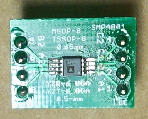
In order to test the sending the thermocouple signal post amplifier over the CAT5 cable I will need to have a stand alone thermocouple amp circuit. since the thermocouple circuit is built onto the HMv4.2 board this makes it a little more complicated. I have some SMD to DIP adapter boards that I plan to solder the thermocouple amp to, then build the circuit on a DIP socket where I can plug that adapter board into....
My question is, will having the thermcouple circuit built onto the HM board cause a problem when I plug this other amp in on the damper end (with a thermocouple only plugged into the damper end circuit)? Should I leave the thermocouple parts off the main HM board for this test or do you think they can both be connected without issue?
 
Yes it will cause a problem with two amps essentially plugged into the same analog line. The AD8495 that has nothing plugged in will drive the line high-ish (~3.2V) and clobber the voltage from the AD8495 with something plugged in. I'm pretty sure it won't damage the other, but they always outputs something so you can't connect them both to the same input.
 
Ok, thanks for that feedback, I will look for an easy-ish way I can lift the output from the onboard thermocouple amp when I am testing the amp over the CAT5 cable so they don't fight each other.....
I guess tomorrow I gotta figure out how to do this SMD soldering, never done that before. I guess I need to get some flux and a smaller soldering iron, damn these things are small!
 
I did the first boards with a soldering iron. The 0805 pieces are pretty easy with some tweezers, but the AD8495 has some really tiny leads that like to bridge. Make sure there are no shorts between pins except for (2-3) and (7-8) which are connected on the PCB. I usually forget to use flux and use standard radio shack solder, so it can't be all that hard. I use one of those head-mounted magnifying glasses though and put my face cancer-inducingly-close.
 
Wow, just did my first SMD soldering job and it went super easy! I soldered the thermocouple amp chip to one of my SMD to DIP adapter boards, started out with applying some flux to the board, had a little too much solder on the iron when I did the first bit, ended up bridging all four legs on that side. So I took advantage of the chip being tacked down and soldered the other side. With a tiny bit of solder on the iron I touched one leg at a time and got all 4 legs soldered clean on the second side. Then I went back with some solder wick and removed the blob of solder from the other side, when I was done all legs were clean and soldered, done deal! I hope it goes as well when I solder the SMD stuff to the HM board.....

EDIT: BTW, went to the new local Harbor Freight and bought one of those magnifying visor deals you wear on your head for $4 bucks, with that on I can actually see the solder joints, without it there's no way I would have gotten this done at all, let alone so easily...
 
Last edited:
Yeah! See it isn't that hard at all. I planned to make a wiki post about it but you beat me to completion. You can plug in a 9V battery to it and test before you build your whole system. Well, now that I think about it I don't know how you will without the rest of the components, but the gist is that if you put 9V to the VCC (7) and GND (2 or 3) pins, you should get close to 9V on the output (5 or 6). Short the input pins (1 and 8) to ground and you should get about 0.125V on the output (or 5mV/C for whatever it is in your room). Note that after soldering the internal temperature of the chip takes a long time to drop so you'll likely see slightly higher voltage for the shorted test.

The chip is good up to 12V or so, so this is well within its operating limits.
 
Here's a pic of the SMD thermocouple amp chip soldered to the adapter board, which is about the size of a pololu driver (14mm X 19mm) and can plug into an IC socket. I plan to use this module as a development tool to experiment with the thermocouple circuits, the circuit can be built on the socket legs and the thermcocouple amp just plugs into the socket to test...
ThermocoupleAmp.jpg
 
On the HMv4.2.3 board, I assume the little dot on the thermocouple amp is Pin1?

EDIT: Never mind, put the part in place and the dots matched up perfectly, the answer to that question must be YES... Got the thermocouple amp soldered onto the HM board without issue, glad I was aware of the two parts where the legs are bridged together though, I might have tried to clean them bridges and screwed things up...
 
Last edited:
You got it. Almost every time I get a set of boards in the mail I immediately see that bridge and think "Oh I messed up", then remember that they are connected.
 
I've used my Thermoworks thermocouple a few times with my HMv4.2.3 and it has worked really well. Last night I did some experimenting with high heat cooking beyond the temperature range I could do with the thermistor probes and ran into an issue....

I had the pit set to 700 degrees, holding nicely for the entire cook. I pulled the food (btw, burgers fast cooked at 700 degrees are awesome!), the HM went into lid mode and closed off my servo damper, then I closed the top vent (leaving the thermocouple in there) and shut the lid . At this point my thermocouple dropped off and I was getting "No Pit Probe" on the HM. Initially I had thought, oh crap, I melted another probe! Then I remembered this thermocouple is supposed to be good to over 2,000 degrees Fahrenheit so I couldn't have melted it?! So I left it in the pit and waited to see what would happen....

Looking at the graph from that cook I see when I opened the lid the thermocouple dropped to about 300 degrees, when I closed the lid (and vents) the thermocouple dropped off at about 300 degrees and didn't even show the upturn in temp, it didn't pick up again until the pit dropped down to about the same 300 degree temp... I found this odd, I thought the HM should at least show the temperature upturn, and should have shown more of the decent in temperature? Is it possible with the fast response of the thermocouple and super hot grill, that the rapid rise in temperature when I closed the lid with the vents closed caused the HM to kinda "tilt" and stop registering the thermocouple? That is the only thing I can think of since my graph doesn't show any upturn in temp at all when I closed the lid?
 
This warrants further investigation but the only thing I can think of is a problem with the thermocouple dynamic range. Around 400F it changes from bandgap reference to full 3.3V reference. I know it goes up past it no problem but maybe it's spazzing out coming back down? That shouldn't be a problem because it already starts at full reference then drops down to bandgap so if it could do it once it should be able to do it again.

It might also be something specific to your topology depending on how your wiring is.


Back
Top