Blue Sky Stepper Damper thread - Breakout from RaspberryPi + LinkMeter blue sky


Dave Casazza

TVWBB Fan
I'm creating this thread to see if we can figure out how to build in a damper or stepper damper, as requested by Bryan.

Here is the start of the thread:

Originally Posted by Dave Casazza
need 3 lines, grnd, fan and solenoid...

D Peart writes:
4 lines actually, because the fan runs high side so you can't use its gnd: 12V, FanGnd, Solenoid, Gnd. (Unless your solenoid can run on 12V in which case you can drive it high side too: 12V, FanGnd, SolenoidGnd).

Bryan writes:
I'd actually prefer if the whole system used stepper motors/servos to simply control the dampers but that would be a pretty radical departure from what we've got. I have to set my dampers depending on what my target temperature is too. The only pin we've got left on a HeaterMeterPi is Digital 7 (non-PWM) re-purposed from SOFTRESET and Digital 8 (non-PWM) re-purposed from LCD_DATA. I hate changing pin functions based on platform though. You should start a new thread to discuss it if you have some ideas though.

(New Thread starts here, throwing it out for discussion)...
 
It appears that the rPi has a single PWM GPIO, pin 12, can we use that? It would be ugly in that the rPi would control the damper, while the AVR does everything else? yuck . . .
 
Let's start with: Specifically, what sort of hardware would be needed to make an electrically controlled damper? Aren't solenoids rated for higher voltage / current than 12V / a few mA? A servo would require 5V and 3 wires, and a PWM. All of these seem outside the reach of our usable interfaces. I'd also considered using a stepper motor, which would also require more wires, but at that point I'd consider it making a secondary device being RF enabled and battery powered or something. So what are the actual hardware options?
 
A good resource for servo info:
http://www.hitecrcd.com/products/

How about a servo running off 3AA batteries with a similar wireless board as the temperature probe. Then we could utilize the wireless interface to control the small PIC on the board just like the temp probe. The servos can run off batteries for a very long time because there is no real load on them. You could probably go months on a set of batteries.

I can see the valve being a simple butterfly valve that is controlled by the servo.

This accomplishes a few things:

1. no additional wires
2. No IO configuration changes
3. Can be built as an add-on and not required
4. flexible so that the servo can be built into all the different smokers out there


dave
 
Last edited:
I think we need to break this down to requirements, and then break out what would be needed to meet the requirements.

I see this as two "phases"

Phase 1) completely 100% dampen the fan when operating, and completely un-dampen the fan when not operationg.
Plus(es):
Simple(r) implementation, possibly can be implemented with less control lines and logic
Possibly easier to implement within existing control logic​

Minus(es):
Does not handle the need to adjust the damper to optimize "base heating convection", will require that the fan have sufficient output to drive heat to anywhere between 180 to 400 degrees, depending on cooking.
May require additional manual venting controls to increase "base heating convection"​

Phase 2) variable stepper motor to control dampening, consistent with fan operating rate
Plus(es):
Ability to optimize/damping for necessary heating control
Minus)es:
Possibly very complicated to both a) implement on the board and b) configure​

Can we look at what would be required for Phase 1) requirements and then what would be required for Phase 2) requirements?

Is there a way we can have forum members vote on what seems to meet their requirements the most?

(Yeah, I'm an organizer type in my day job) :o
 
Last edited:
I think that a fan damper should be an 0%/100% thing I can't see any advantage to modulating both the fan and a damper in the blower output at the same time that can't be achieved with just better fan control and something to shut off airflow completely. In my cooks, the only thing I change is the output vent based on temperature. I need to do a test with the bottom completely sealed and the top wide open and see if the fire goes out to see if any degree of control could overcome an unrestricted exhaust.

What I was thinking with this design was a fan replacement[/] that dampered natural convection through the grill by opening and closing the intake vent.

Servos aren't a bad idea but servos require "holding current" i.e. power to hold them in their current position. This would probably outshadow the 20-25mA of current draw coming from operating the RF receiver and AVR and make a set of AA batteries last at most one cook? This requires some experimentation because I don't know crap about them.

I've also considered using the temperature difference from the heat coming out of the chimney to ambient to power some peltier thermoelectric modules to possibly generate the current used to power a device controlling a chimney damper.
 
I agree about the 0%/100% thing...

Maybe we are thinking about this the wrong way... how does the auber 6.5 cfm fan actuate their shutter?
 
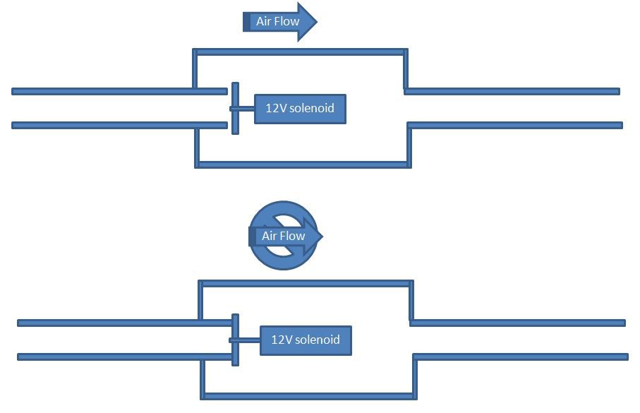
if we go 0%/100% then nothing has to change at all in the hardware. Get a 12V solenoid, hook it to the 12V fan supply and when the fan runs, the solenoid will be powered. When the fan is off, the solenoid will as well.

Something like this is an already complete system:
http://www.china-solenoidvalve.com/12v_solenoid_valve.htm

or
http://www.amazon.com/dp/B007R9U9BM/?tag=TVWB-20

If we had 24V this would work:
http://www.amazon.com/dp/B00004S1V3/?tag=TVWB-20

Maybe we can find a 12V replacement solenoid for the sprinkler system

dave
 
The fan's 12V is always hot, and the ground is switched on and off at 490Hz, so I don't know if that will work. I could be wrong about all this because I am just a programmer, so just tell me I am wrong if that's the case.
 
The fan's 12V is always hot, and the ground is switched on and off at 490Hz, so I don't know if that will work. I could be wrong about all this because I am just a programmer, so just tell me I am wrong if that's the case.

Ah, I didn't know we were switching the ground, it should really matter though the main issue would be to make sure the solenoid didn't chatter. That could be overcome with a capacitor to smooth things out for the solenoid.

Here is an idea for the air valve. The limitation is the size of the solenoid, but I think this design is something we can build. I'll take a piece of PVC pipe mount the solenoid inside it, then use a reducer and slip another piece of pipe into that. The solenoid would then effectively "cap" the end of the smaller pipe to close it off. Here is a picture.

AirValve.jpg


one idea,
dave
 
OK my cook yesterday was a real PITA, I could not keep the temp. down enough. So I looked around and found this guy:
http://www.ebay.com/itm/1-2-Gravity...675?pt=LH_DefaultDomain_0&hash=item43b2e2436b

Normally closed, gravity feed (no minimum operating pressure), 12V solenoid valve at 500mA. The 500mA has me a little concerned.

The power supply for the router is 12V at 1000mA.

The solenoid take 500mA
The blower takes 300mA
The router takes ? (anyone ever plug one of these into a kill-a-watt type meter)
The HM takes ?

I'm not feeling good about the size of the power supply . . .
 
The orifice is only 8.5mm. I would be concerned with the pressure drop across that and would sort of flow rates you could expect from the fan.
 
I think we need to find a low current draw solenoid with a 2-3 cm push or pull length... once we come up with options around this design aspect, we could see if we could mount or 3D print a solution. Can we find a 300ma solenoid?
 
Expensive... seems like only you and I might do this ;)... Good job finding one... I'll have to look for something less expensive for inclusion in the project.
 
Expensive... seems like only you and I might do this ;)... Good job finding one... I'll have to look for something less expensive for inclusion in the project.

If you find something please let me know. That is the only 1" stroke 12VDC solenoid I can find.

dave
 
Here is another idea.

We could use a servo. It would be controlled by a simple 555 timer to open to a set position, the 555 timer would hold it in that position. We could power the servo/555 timer combo with the 12V fan supply.

Basically we would reduce the servo to being a solenoid. It will use less power, can be had for < $10. The downside is that there will be some control circuitry to put together and a board to support it. The board could easily be constructed at home by anyone with a toner printer/photocopier.

If we could construct a simple butterfly valve and 3D print it, that would be perfect :)

dave
 
I think short term, this might be the best way to go...

Long term - maybe a move to the arduino platform with more pins might be in order?
 
Last year I made a gravity operated flapper that covered the blower opening in the Blower Adapter Housing[SUP]TM[/SUP] (AKA rabbit food dish). The hinge was a Dubro nylon RC plane hinge, worked a little bit to have no drag. The flap that covered the opening was some very thin aluminum epoxied to the hinge. The angle of the housing provided the gravity closing force though it could have been done other ways. To pop open the flapper the blower had to be cranked up a little bit more than otherwise though once it did it would pop wide open. It was a pretty light weight arrangement.

It did work but ultimately I removed it:

  • BBQ juices dripped onto the hinge and I didn't want to remove it to clean it only to have it happen again. This problem could have probably been avoided by mounting the thing in a different orientation on the WSM bottom shell but this was probably the main reason - laziness.
  • I wasn't happy with the increased blower air volume needed to pop open the damper. I'm used to the blower running at very low RPM at times. Not so with the gravity operated flapper. No big deal really.
  • I figured an all or nothing would be the ticket. I looked around at some RC servos to devise some simple mechanical arrangement - no joy.
  • Ultimately the mechanical ??? and my lack of a real problem controlling high temps lead to a "meh" moment - I moved on to other projects.

Still, I like the idea so I'm all in on this one.
 
Hey I tried a Dubro nylon hinge as well, thinking it would be like a friction-free flapper that would magically open and close with a small amount of fan power. Unfortunately, those hinges are far from friction-free and they stick in whatever position they'd move to. I tried putting it inside the fan tunnel to protect it from bbq squeezins.

And remember regarding any sort of powered solution, you'll need two more wires. If you reuse the 12V line, you're still going to need a ground and "signal" line.

Some folks have already asked about "upgrading" to the bigger ATmega(whatsitcalled) but that thing is huge and would break all sorts of compatibility and I'm not sure if it would even make a significant difference in control.


Back
Top