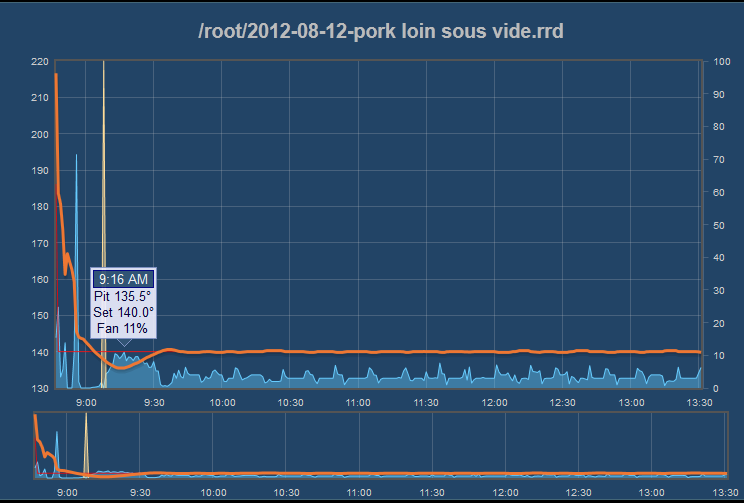
That makes sense.
Just for clarity.... some of this information is duplicated in another thread, but here goes:
PWM:
If you run above 10% (by default), the PWM is in "normal" mode, with a frequency something like 500Hz or whatever the Arduino puts out on the PWM pins. This is
similar to a true "analog" value, which is why arduino calls it an "analogWrite()". So, at 50% power requested, the output pin is a square wave with a period of .002 seconds, where it is on .001 second and off .001 second.
SRTP:
Once the "requested" fan speed (or in this case heater power) goes under 10% (by default), the PWM of the pin gets set at 100% duty cycle, but the pin is then cycled on and off much slower than before. The ratio of the on time to the off time is still equivalent to the duty cycle, say 5%, but it is slowed down to be on for 0.5 seconds of every 10 seconds, so the average is 5% on time. The code is such that we only have 6 "steps" of resolution on the output, but hopefully we can increase that with a small code change. For the fan it is just fine, but for the heater we seem to be running in the < 10% mode, so increased time resolution here
might smooth the line out. I have been calling this mode SRTP, for "Split Range Time Proportional", which is a term I've become familiar with in the PLC world... It makes this topic easier to discuss in writing if we have some nomenclature defined.
Another tidbit about SSR (Solid State Relays)...
SSRs do not provide proportional control, at least not the way we are using them here. If you look inside a standard 3-35vdc triggered SSR, you'll find a bit of circuitry, an opto-isolator, and an SCR. The SCR is our "problem" here, since they will only switch in phase with the 60Hz sine wave of the mains voltage you apply it (or 50Hz in some places). So, the ability to define our PWM duty cycle in increments less than 1/60 second does little to no good. It will make for a nice flicker for Halloween lights, but that is not so great for powering a heating element. I imagine it makes a lot of excess heat as well. Just to be thorough, you can provide proportional control, but that involves syncing to the 0 crossing point of the sine wave and offsetting by a phase angle. There are chips that provide the timing in a microcontroller friendly way, but this is very much overkill for our setup. If someone finds a reason to control lights with the heatermeter, that is a different story all together.... Anyway, that is why we need the "SRTP" mode, so we get predictable and efficient control of the heater.
Why?
For those who do not already know, the SRTP mode was created by Bryan to handle the fact that most of these blower motors are not brushed DC motors, they are 'brushless DC' (BLDC) motors... They have an MCU on board that does some magic to make the fan go, and they need a minimum voltage to run. The range they do not like to run in, we avoid via the SRTP. Just going out on a limb, I think the heater stuff will be best kept in SRTP mode at all times, especially if the resolution is increased.
Did anyone actually read all that? I added 'topic headers' for easy skimming


