Hello so after a long time of wanting to do this project I finally jumped in. I'm probably more excited than I should be to get this up and running, but it's been a fun little project. And I'm an engineer/geek so I see so many uses for a device like this. I already have parts for a crock pot sous vide and my eye on a couple of things to make it a stand alone system.
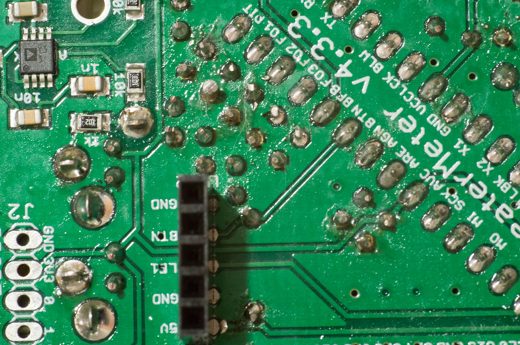
Over the weekend I managed to get the board together and running. But the temptertures I'm getting are pretty far off from what they should be. The thermocouple is around 3-5F off, but that's more or less calibrate-able due to linear curve. However probes 1-3 are way off, 10-25F. I have two thermoworks probes that I'm using, and from switching positions at known temperatures (room/boiling water) I'm pretty sure the issue is with the heatermeter not the probes. And yes I did switch to the thermowork probe setting in the web UI.
It could be a fair assumption that I broke a component (or more) while soldering, soldering not a skill I use much (or at all). I actually had to buy a new soldering iron because the old one I had (borrowed) was just not working. With a new one I did much better (temperature control helped tremendously) with soldering but still have some issues especially with ground plain connections. So poor connection somewhere, or I over heated something would not surprise me.
How do I go about debugging the board, I started with getting the voltages off of the test pads for the probes, but I don't know where to go from there, or really what the readings should be. (3.3V +- some error right?) Without probes attached I get,
"3.3" - 3.27 V
"0"- 3.229 V
"1" - 3.25 V
"2" - 3.258 V
"3" - 3.244 V
So in the range of 1-3%error, is this too much or is that within spec?
I do get a voltage drop after attaching a probe.
FIY I'm using rev 4.3
Thanks for your help
-Dave