Rotordamper Aux. TC board with two probe jacks, blower and servo connections


John Bostwick

TVWBB Wizard
Updated Rotordamper Aux. TC board v3.4

Edited

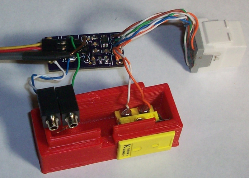
The final version of the Rotodamper TC board is available on OSH if you would like to build one. 3 boards $6.50 include shipping

AUX. TC board v3.4

The parts needed to make the board are mouser parts
You can run the board with just the TC amp circuit without using the 3.3v regulator, and OPamp circuit

3.3v circuit3.3v regulator

OPamp circuit1m trimmer

OPamp circuit1m resistor

OPamp circuitOP777

You also need the same components for the Heatermeter TC amp circuit, 2 inline jacks, a Rj45 connector(same as Heatermeter) and 3 more .1 caps smd resistors(same used in Thermocouple circuit)

Also needed is a 5pin header, same as the Heatermeter lcd(you should have a left over piece from the LCD)

The parts that are needed and the board will improve over time, as the Trimmer is a little hard to solder, I moved it to an edge to make a little easier not to melt it. Also, the probe jacks may or may not be slotted as to round. If they are around then you may need to make the ground pin1(first pin on both, next to edge) thinner by clipping off a little on the side, so that it fits in. They can fin in as is, but its very very tight or you can ream out the hole a little, also. Will be looking for a fix. And I will be looking for cheaper components, So, I will just update the links and board as needed to better parts.

Also, this can be used on Rotodampers that have already been made but, you will need to do some custom work on the case to make it fit correctly. I will hopefully have an easy how-to post here soon. Ralph is making a new Rotodamper that will work with the board.
 
Last edited:
Good news, it works perfect. Although it works, if you do have a Rotordamper it does need some modifying to get the Cat5 connector to fit and needs a certain type of connector found at Home Depot. The board will be changed to add a different type of jack for the probes the can be screwed to the RD, and Ralph and I will try to add a few more things to the Aux. Board as time goes by.

Another benefit to using this Aux board you can leave 4 Probe jacks on the HM and add a TC from the Aux board to be able to switch from a probe to a tc, if needed.
 
aw2910.png


V.2.1 Aux board
-changed the probe jacks to Mouser Part #: 161-3403-E(pic on mouser not correct)
-changed the order and added the TC to a single header, so no more cutting the servo wires to connect it to the Heatermeter.
-added the Cat5 connector to the board
- the board is shorter and a bit wider 1.38x0.67 inches (35.10x16.89 mm).
 
Last edited:
Looking forward to this John. Thanks to you and Ralph for all your efforts.
Love the idea of "leave 4 Probe jacks on the HM and add a TC from the Aux board". That gives much more versatility to the whole heatermeter project.
I assume that all that we will have to do is change the config to TC in the HM?

Well, it's not quite that easy. If you have 4 standard probes on your HM (no TC) then that means you have a pullup resistor on the board for the pit probe, which you cannot have in place when you run a TC (internal or external). So you would have to rig up a way to switch that pullup resistor in/out to switch between internal standard probe and external TC.
 
Well, worst case a small toggle would probably do the trick or two different HM's.
Whatever works!!
 
Yes, lift the pullup resistor and use a small toggle to connect/disconnect it, that would work fine to switch between TC or standard pit probe.
 
...or just use the feature in the latest snapshot firmware (I assume will be rolled into the next official release) which will make Food Probe 1 function as the pit probe when Probe 0 is disabled. You would only have 3 probes (Pit plus 2 food) but I think that should be enough, better than having to keep two HM's on hand...
 
I think Ralph will like this, I did some work on a v.3 board and added a TC reference voltage and a 3.3v regulator to be able to run the TC amp at 3.3v instead of 5v

2lbm2o5.png


Edited: Changed the Cat5 orientation, it was backwards, lol. I realized it when I was building a Heatermeter and notice the support holes were towards the edge of the board. oops. Atleast, Laen at OSH Park let me fix the mistake.
 
Last edited:
I got mine assembled, Nice work!

Here's a pic..
JB_TCAmp.jpg


I popped the CAT6 connector open and soldered the wires to the board, that worked fine and it snapped into the roto damper well with a low profile. Since the board wasn't going to fit into the RD with the probe jacks mounted I put a 3-pin right angle header where the probe jacks were to connect the servo, nice... or so I thought... Turns out I was having a hard time fitting everything in the box and pressing it on the roto damper, so I wired the servo straight to the board and cut off the probe jack end of the board to make the whole thing smaller. With the smaller board things pressed together nicely...
Everything worked on the first power up, I wired it for 2 food probes with the Thermocouple Pit Probe, running the TC amp from the +5v so I could have the second food probe. Seems to be working great, room temp reads right, tracks well with the thermoworks probe in a glass of hot tap water. I haven't seen the noise icon at all, tested the servo and blower motion and it seems to be running real clean! Using a short CAT5 cable now, will have to do some testing over a longer cable and broader temp range later....
 
Last edited:
I really need to get a new Thermocouple. The one im using to test with, is an Auber 4 inch that has the attached clip. But the problem is that the thermocouple fell apart and now the wires are exposed at the junction. So, now when I use the thermocouple in fluctuates to every little temp difference. It might read 100.4 and then a second later it will be 100.8 and then its back down to 100.1. Usually it stays within a degree or so. Soon as I put the junction between my fingers its supper stable.

Anyways, Im glad it works, as it works great on mine too. What I did with the cat5 jack was put the 4 wires(in the back row) on one side and 4 on the other side, so that I would have some underneath and some above.

The next version I have being made has the cat5 jack on the board and has the cheaper mouser screw probe jacks. I should receive that board next week.
 
Just ordered version 3.2
Top
dwwh0h.png


Bottom(not to scale)
244nvd3.png

Version 3.2
-added TC jack on the board
-added an Ref. opamp circuit(to be able to read temps below 32 degrees)
-added a 3.3 regulator and needed components
-added jumpers to run TC amp at 3.3v or 5v and to bypass the Regulator and/or Opamp circuit
 
Last edited:
pretty good, I was suppose receive version 2 today, but it was a no show. Version 3 with everything included on one board of about 40mmX20mm(3.3V,TC Jack, Cat5 Jack, 2 probe jack, and an adjustable Ref circuit for the TC amp) should be arriving within a couple weeks or so.
 
Great news if you need a Naperville guy to put it through a work out let me know. I'd love to put this baby to the test on my stump's at the Winter burn off next month.
 
Thats great. I can't wait to be able to get one of these from my RD. Will we have to order a whole new RD or will there be a add on case for the current version?
 
Thats great. I can't wait to be able to get one of these from my RD. Will we have to order a whole new RD or will there be a add on case for the current version?

With the current version, it will need to be retrofitted. I will be doing one for somebody soon, which will involve some bondo and a nice paint job. Ralp will be receiving the Version 3 board soon and will be making a new case to make adding the board a piece of cake. The servo just connects using the pin header that's already connected to the servo when you get them. The version(3) that will be built for the next Rotodamper will have a soldered TC jack on the bottom and the thermocouple amp will have the option to either run with 3.3v or 5v and will have adjustable Ref. pin on the amp to be able to go lower on the TC, although most wont need that and will be a optional.

wklllh.jpg
 
I really need to get a new Thermocouple. The one im using to test with, is an Auber 4 inch that has the attached clip. But the problem is that the thermocouple fell apart and now the wires are exposed at the junction. So, now when I use the thermocouple in fluctuates to every little temp difference. It might read 100.4 and then a second later it will be 100.8 and then its back down to 100.1. Usually it stays within a degree or so. Soon as I put the junction between my fingers its supper stable.
.

Apparently I need some new ones too. Following the two recent 4.2.4 TC builds (boards from Bryan, with the TC components already installed) I noticed this behavior. I had purchased 4 thermocouples from Auber and they flop around every second or so within a 1 degree range. I figured this was normal and the high-accuracy that we were looking for from the thermocouple.

Is this abnormal behavior? Both of my new HMs do this with all four of the thermocouples.


Back
Top