adafruit thermocouple breakout board


John Bostwick

TVWBB Wizard
I have been playing with an adafruit tc board and I grounded pin 2, I also removed the diode that was attached to pin 2. I also replaced the resisters that were at each lead to the thermocouple from 100k to what's on the hm, 10k.

My question is my temperature is exactly +10° off.

What else could I do to get a more accurate temp.
 
The datasheet for the AD849 does include information about output calibration, you should give it a read (it is linked at Mouser)
Basically you can use the REF pin to fine tune the TC output by applying a very small offset voltage. Since winter has hit and my TC is bottoming out at 37F I have started looking into what I can do to make the TC read down into sub zero temps so I can use it to monitor the weather a bit. A simple voltage divider is not recommended to supply the REF voltage, it should be buffered as well. From the AD849 datasheet recommendations I came up with this circuit that I am going to experiment with to supply the offset voltage (and make my TC register sub zero temps), the same or similar circuit could be used to make fine adjustments in the TC output.

Here is the diagram of the circuit I am going to test (when the parts get delivered):

TC_Offset_Ref.jpg


I haven't tested it yet or anything, but will report back when I do.
 
Hey John, are you powering the Adafruit board by +5v or +3.3v? Not sure if you read the little update I posted recently on my roto damper thread, but I had been experimenting with running the external TC amp with various voltages and found when I power it with +5v the temp readings jump up a bit, and when I power with +12v it jumps up even more.... When I power it with 3.3v (like the ATMega) the external TC amp reads the same as the internal TC amp and the rest of the probes.
 
Yeah, I have almost given up on the adafruit board and went back to the 4.1 frankenboard. I do have it powered with 5v(uds.servebeer.com) Its very stable atm, no noise. I might just add an offset. My problem is with the cat5 connectors. I cant seem to get good connections when I insert the wires into the connector. So, I am going to solder the wires directly to one that I have taken apart. I use the wire tool that comes with them to push the wires in and I don't get a good contact and I am constantly having to monkey with them
 
Are you using solid or stranded CAT5 cable? You want solid for punch down connectors....
I've been punching down solid wire lately and haven't had any problems, but when I started out I used to cut the plastic away from the punch down knives and solder the wires on to be sure they get a good connection. I still tend to cut the plastic away from the ground on the corner and solder the wires in since there are a couple wires of different thickness that connect there, other than that punched down wires work fine for me.
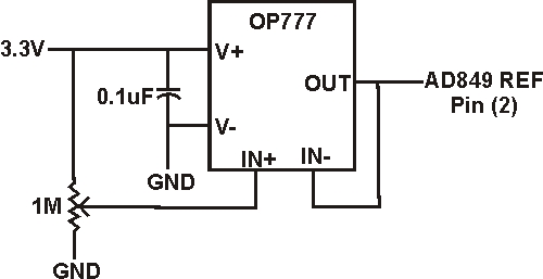
On the offset, I think if you go back to powering the amp with 3.3v your TC will read the same as the other probes. That said, I am moving in the direction of using a tunable offset voltage and then setting an offset for the TC in the HM Config so the TC will work down into the sub zero range. I hope to have the circuit posted above built up this week some time. BTW, I am going to use a multi-turn (5) potentiometer for the offset voltage adjustment for finer more gradual adjustment.
 
I have a question abut the Tc board, in general. Would it be ok to cover it with hot glue, or would that lead to a temperature difference. Reason asking is I would like to add some protection and support to the wires when I stuff it in the RD. I plan to do the same on the HM for the connections on there too.
 
IDK, I guess if the AD849 generates any heat it might build up under the hot glue and effect the temp reading. I would use the glue only on the area around the wires or glue the wires to the back side of the board instead of covering the AD849 with hot glue. Though I haven't found a need to do this and never had a problem. There is a plenty of room in the roto damper TC box to fit the amp in comfortably and once it is in there nothing moves....
 
I thought that the glue would cause some problems with detecting heat correctly. I doubt it makes enough heat on its own. Anyways, since this going to someone else, I want to protect it as much as possible from shock(dropping) and anything else that may cause stress on connections.

Tonight, after work going to connect everything and do another test at 5v and 3v and I will see if using the offset will be OK at higher temps.
 
...

Tonight, after work going to connect everything and do another test at 5v and 3v and I will see if using the offset will be OK at higher temps.

Hi John,
Any results with the lower offset voltage ?

My TC setup seems to be pretty close to my Thermoworks probes... probably within the same 10 degrees you mention. I will have to look for a graph showing an ambient temp comparison.

I have a couple of issues using the Adafruit board in my v4.1.4 HM setup as well. I have the Adafruit TC amp and a I2C ADC on a breakout board... using 5v for a reference. I have a high temp thermocouple that has a metal probe casing with the TC leads insulated by ceramic insulators. The TC is right near the charcoal grate in a heat transfer tube.

My firebox goes over 900 degrees at times and that exceeds the HM max... then I see the fire temp "flatline" around 275 degrees (Note that I have a lot of noise) and have had mixed results with grounding and rebooting the HM.

Sometimes the fire temp will recover and report correctly after a power cycle of the HM. A time or two, it will recover after rebooting the AVR.

Would like to get this sorted out if the ref voltage may help.
 
Last edited:


Back
Top